INSTRUMENT CLUSTER
Instrument Cluster Wiring Diagram (1 of 2) for Hyundai XG350 2003
 https://portal-diagnostov.com/license.html
Automotive Electricians Portal FZCO
Automotive Electricians Portal FZCO
https://portal-diagnostov.com/license.html
https://portal-diagnostov.com/license.html
Automotive Electricians Portal FZCO
Automotive Electricians Portal FZCO
List of elements for Instrument Cluster Wiring Diagram (1 of 2) for Hyundai XG350 2003:
- (on firewall, near throttle housing) g11
- (on left "a" pillar, near passenger compt junction block) g06
- (on left front of engine compartment) engine compartment junction block
- (on right "a" pillar, near crash bar) g05
- 1 input
- 2 input
- 3 input
- 4 input
- 5 input
- A11
- Abs indicator
- Anti-lock brakes system exterior lights system
- Brake warning indicator
- C44-1
- C44-2
- C44-3
- C44-4
- Charge indicator
- Check eng ind
- Cruise control system
- Cruise indicator
- Data link connector (dlc) (below left side of dash)
- Door ajar indicator
- Engine coolant temperature (ect) gauge
- Engine coolant temperature sensor & sender (on rear of engine)
- Eps control module (center of dash)
- Etacm
- Exterior lights system
- Front fog indicator
- Fuel gauge
- Fuse 10a
- Fuse 23 10a
- Fuse 25 10a
- Headlights system
- High beam indicator
- Hot at all times
- Hot in on or start
- I18-1
- I18-2
- I18-3
- Ign detect sig
- Ignition failure sensor (on upper left rear of engine)
- Illumination (6 bulbs)
- Indicator control circuit
- Indicator srs
- Instrument cluster
- Interior lights system
- J/c i20
- Jc01
- Ji01
- Ji02
- Jm01
- Jm02
- Jm04
- Jm09
- Left turn indicator
- Low fuel indicator
- M33-3
- Malfunction indicator lamp (mil) "check engine"
- Oil pressure indicator
- Oil pressure switch (on left front of engine)
- Passenger compartment junction block (behind left end of dash)
- Pcm (behind lower center of dash)
- Pnk
- Right turn indicator
- Seat belt indicator
- Short connector "a"
- Speedometer
- Starting/charging system
- Stop lamp failure indicator
- Tachometer
- Tan
- Tcs indicator
- Trip computer circuit
- Vehicle speed sensor (on top right side of transaxle)
- Vss input
Instrument Cluster Wiring Diagram (2 of 2) for Hyundai XG350 2003
List of elements for Instrument Cluster Wiring Diagram (2 of 2) for Hyundai XG350 2003:
- (on firewall, near throttle housing) g11
- (on left "a" pillar,
- (on right "a" pillar, near crash bar) g05
- Brake fluid level sensor (on brake fluid sensor)
- Cluster
- Digital clock (w/o trip computer)
- Dim input
- Diode z01 (behind upper left side of dash)
- Engine compartment junction block (on left front of engine compartment)
- Etacm
- Foot parking brake switch (above parking brake pedal, on bracket)
- Fuel level float
- Fuel sender
- Fuel sender & fuel pump motor
- Fuse 21 10a
- Fuse 23 10a
- Fuse 25 10a
- Fuse 28 10a
- Gauge sender
- Ground
- Hot at all times
- Hot in on or start
- Ims control module (below driver's seat)
- Interior lights system
- J/c i20
- J/c m09
- Jc01 e6
- Ji01
- Ji02
- Jm01
- Jm04
- Jm06
- Jm09 a11
- Junction block) g06
- M110-3
- M33-3
- Memory pwr
- Nca
- Near passenger compt
- Normal
- Parking position
- Passenger compartment junction block (behind left end of dash)
- Pnk
- Red
- Seat belt
- Select
- Select switch
- Short connector "a"
- Sport mode switch
- Start/on in
- Thermistor
- Transaxle range switch (on left side of transaxle)
- Transmissions system
- Trip computer circuit
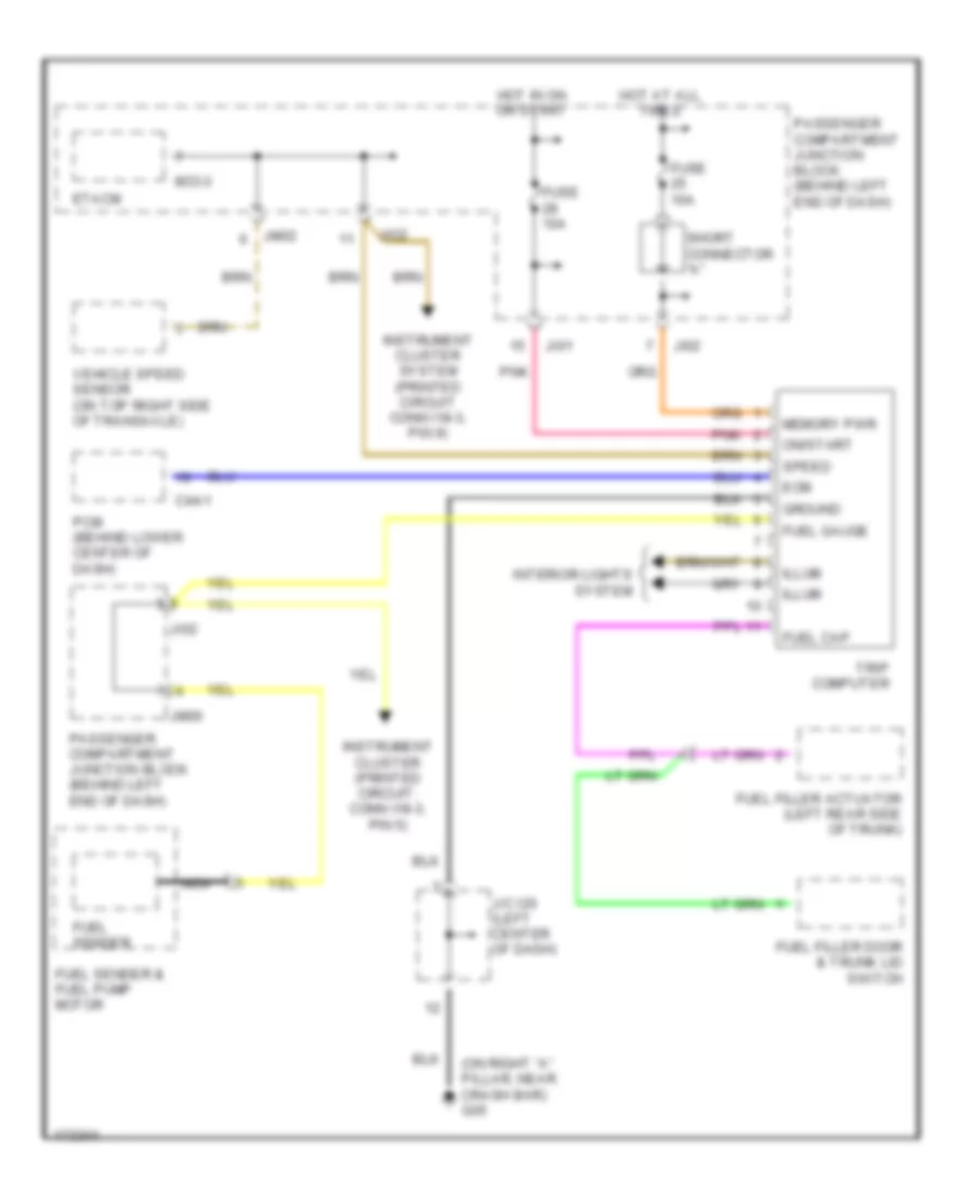
Trip Computer Wiring Diagram for Hyundai XG350 2003
List of elements for Trip Computer Wiring Diagram for Hyundai XG350 2003:
- (on right "a" pillar, near crash bar) g05
- C44-1
- Ecm
- Etacm
- Fuel cap
- Fuel filler actuator (left rear side of trunk)
- Fuel filler door & trunk lid switch
- Fuel gauge
- Fuel sender
- Fuel sender & fuel pump motor
- Fuse 10a
- Ground
- Hot at all times
- Hot in on or start
- Illum
- Instrument cluster (printed circuit: conn i18-3, pin 5)
- Instrument cluster system (printed circuit conn i18-3, pin 9)
- Interior lights system
- J/c i20 (left center of dash)
- Ji01
- Ji02
- Jio2
- Jm02
- Jm06
- M33-3
- Memory pwr
- Nca
- On/start
- Passenger compartment junction block (behind left end of dash)
- Pcm (behind lower center of dash)
- Pnk
- Short connector "a"
- Speed
- Trip computer
- Vehicle speed sensor (on top right side of transaxle)

 Čeština
 Dansk
Dansk Deutsch
 Ελληνικά
 English
 Español
 Suomi
Suomi Français
 Français
 עברית
עברית Hrvatski
 Magyar
 Italiano
 日本語
日本語 한국어
한국어 Nederlands
 Polski
 Português
 Português
 Română
 Русский
 Slovenčina
 Slovenščina
 Svenska
 Türkçe
 中文 (中国)