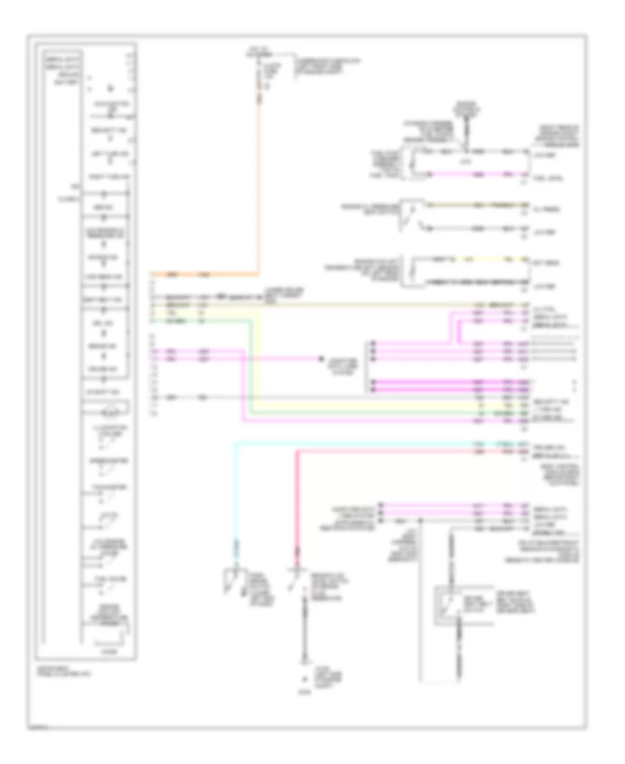
INSTRUMENT CLUSTER
Instrument Cluster Wiring Diagram for Isuzu i-290 S 2008
List of elements for Instrument Cluster Wiring Diagram for Isuzu i-290 S 2008:
- (chassis harness, 39 cm before fuel pump & sender assembly)
- (or tan)
- (right rear of engine compt) engine control module (ecm)
- (under driver seat carpet) g300
- A19
- A31
- A38
- A39
- A41
- A42
- A44
- A45
- A47
- Abs ind
- Air bag ind
- Battery
- Body control module (bcm) (behind right kick panel)
- Brake fluid level switch (on brake fluid reservoir)
- Brake ind
- Brk fluid lvl
- Chime
- Class 2
- Clstr fuse 10a
- Computer data lines system
- Cruise ind
- Dr belt sw
- Driver seat belt buckle (right side of driver's seat)
- Driver seat belt switch
- Drl ind
- Ect sens
- Engine controls system
- Engine coolant
- Engine coolant temperature gauge
- Engine oil pressure (eop) switch
- Fuel gauge
- Fuel level
- Fuel pump & sender assembly (top of fuel tank)
- G105
- Ground
- High beam ind
- Hot at all times
- Ign
- Illumination (4 bulbs)
- Inflatable restraint sensing & diagnostic module (beneath center console)
- Instrument panel cluster (ipc)
- J201
- J310
- J311 (body harness, 24.5 cm from g302 breakout)
- Jx105 (left side of engine compt)
- L turn ind
- Left turn ind
- Low engine oil pressure gauge
- Low engine oil pressure ind
- Low ref
- Malfunction ind
- Mil ctrl
- Nca
- Oil press
- Park brake switch (lower left end of dash)
- Pnk
- Prk brk sw
- R turn ind
- Right turn ind
- Seat belt ind
- Security ind
- Serial data
- Speedometer
- Tachometer
- Temperature (ect) sensor (on left rear of engine)
- Underhood fuse block (left front side of engine compt)
- Up shift ind
- Volts
 Čeština
 Dansk
Dansk Deutsch
 Ελληνικά
 English
 Español
 Suomi
Suomi Français
 Français
 עברית
עברית Hrvatski
 Magyar
 Italiano
 日本語
日本語 한국어
한국어 Nederlands
 Polski
 Português
 Português
 Română
 Русский
 Slovenčina
 Slovenščina
 Svenska
 Türkçe
 中文 (中国)
 English