Čeština
 Dansk
Dansk Deutsch
 Ελληνικά
 English
 English
 Español
 Suomi
Suomi Français
 Français
 עברית
עברית Hrvatski
 Magyar
 Italiano
 日本語
日本語 한국어
한국어 Nederlands
 Polski
 Português
 Português
 Română
 Русский
 Slovenčina
 Slovenščina
 Svenska
 Türkçe

INSTRUMENT CLUSTER
Auxiliary Gauges Wiring Diagram for Mitsubishi 3000GT Spyder SL 1996


List of elements for Auxiliary Gauges Wiring Diagram for Mitsubishi 3000GT Spyder SL 1996:
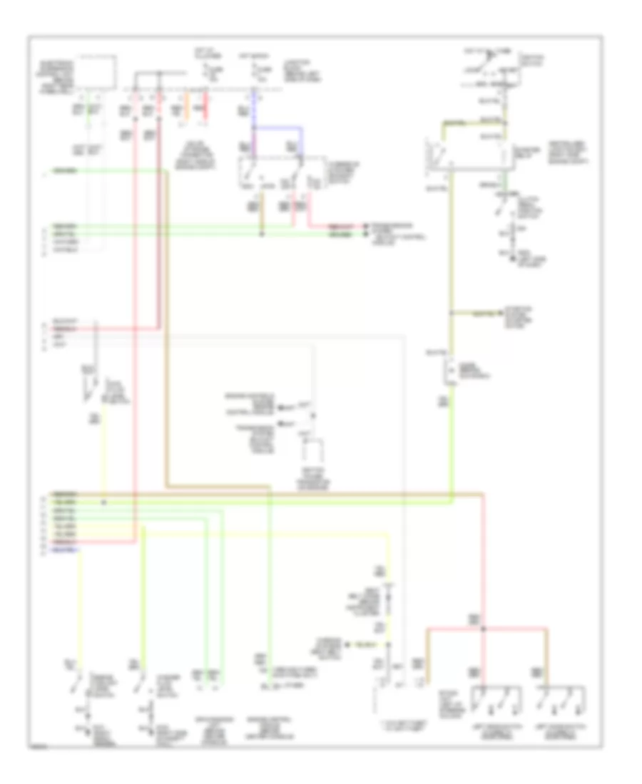
Instrument Cluster Wiring Diagram (1 of 2) for Mitsubishi 3000GT Spyder SL 1996
List of elements for Instrument Cluster Wiring Diagram (1 of 2) for Mitsubishi 3000GT Spyder SL 1996:
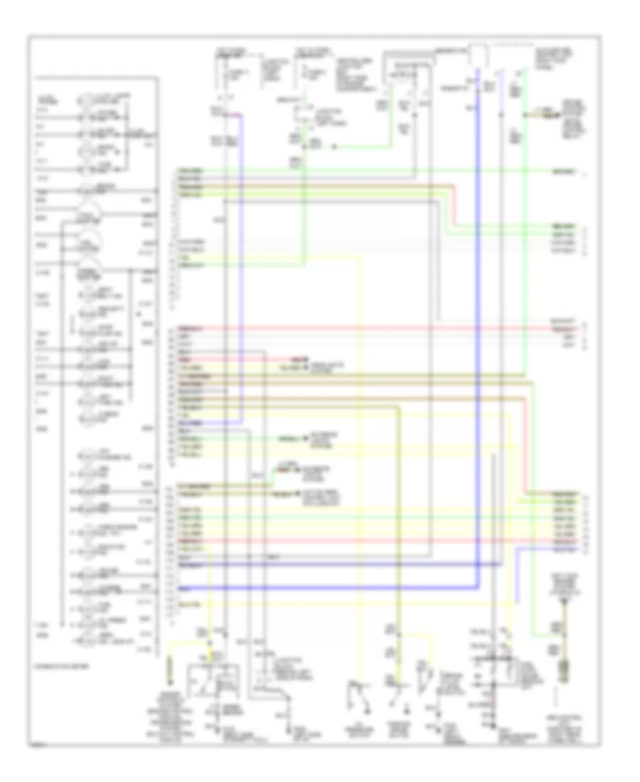
Instrument Cluster Wiring Diagram (2 of 2) for Mitsubishi 3000GT Spyder SL 1996
List of elements for Instrument Cluster Wiring Diagram (2 of 2) for Mitsubishi 3000GT Spyder SL 1996: