INSTRUMENT CLUSTER
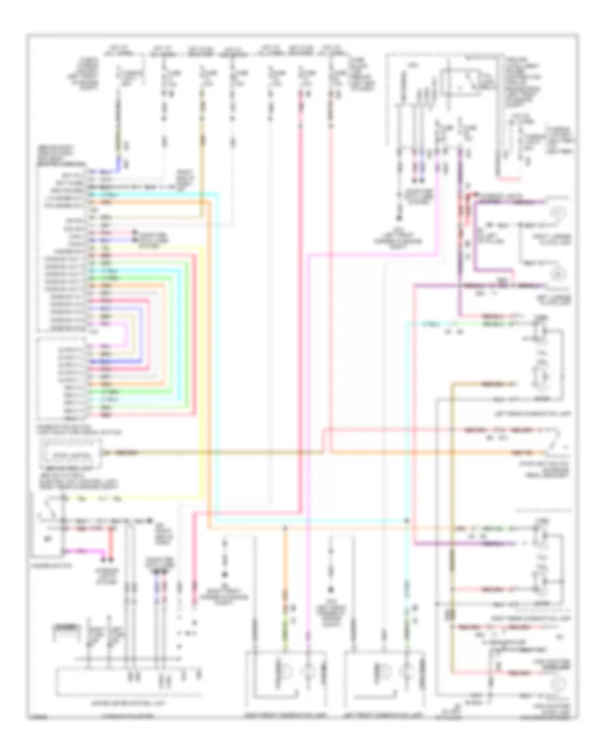
Instrument Cluster Wiring Diagram, with Head-Up Display (1 of 2) for Nissan 240SX SE 1994
 https://portal-diagnostov.com/license.html
Automotive Electricians Portal FZCO
Automotive Electricians Portal FZCO
https://portal-diagnostov.com/license.html
https://portal-diagnostov.com/license.html
Automotive Electricians Portal FZCO
Automotive Electricians Portal FZCO
List of elements for Instrument Cluster Wiring Diagram, with Head-Up Display (1 of 2) for Nissan 240SX SE 1994:
- 2.0l m/t
- 2.5l m/t
- B7 (in left "b" pillar)
- Backup
- Backup light switch (on transaxle)
- Cvt
- E13
- Fuse 10a
- Fuse block (j/b) (behind left end of dash)
- Hot in on or start
- Left rear combination lamp
- M4 5p
- Park/neutral position (pnp) switch (left side of transaxle)
- Pnk
- Right rear combination lamp
- Transmission range switch
Instrument Cluster Wiring Diagram, with Head-Up Display (2 of 2) for Nissan 240SX SE 1994
List of elements for Instrument Cluster Wiring Diagram, with Head-Up Display (2 of 2) for Nissan 240SX SE 1994:
- (behind right side of dash) bcm (body control module)
- (right end of dash) m57
- 12p
- Abs actuator & electric unit (control unit) (right rear of engine compt)
- Abs control unit
- Acc sw
- B30
- B7 (in left "b" pillar)
- Bat
- Bat (f/l)
- Bat (fuse)
- Buzzer
- Can-h
- Can-l
- Comb sw in 1
- Comb sw in 2
- Comb sw in 3
- Comb sw in 4
- Comb sw in 5
- Comb sw out 1
- Comb sw out 2
- Comb sw out 3
- Comb sw out 4
- Comb sw out 5
- Combination meter
- Combination switch (lighting & turn signal switch)
- Computer data lines system
- Cpu
- E10
- E13
- E15 (left front corner of engine compt)
- E25
- E39
- E42
- E45
- E46
- E9 (right front corner of engine compt)
- Fuse
- Fuse & fusible link box (left front of engine compt)
- Fuse 10a
- Fuse block (j/b) (behind left end of dash)
- Fusible link box (battery) (at battery)
- Fusible link d 60a
- Fusible link j 50a
- Gnd
- Gnd (power)
- Gnd (signal)
- Hazard sw
- Hazard switch
- High mounted stop lamp
- High mounted stop lamp (w/o rear spoiler)
- Hot at all times
- Hot in acc or on
- Hot in on or start
- Ign
- Ign sw
- Input 1
- Input 2
- Input 3
- Input 4
- Input 5
- Interior lights system
- Ipdm e/r (intelligent power distribution module engine room) (left front of engine compt)
- L flasher out
- Left front combination lamp
- Left license plate lamp
- Left rear combination lamp
- Left turn ind
- M100 m40
- M17
- M18
- M20
- M57 (right end of dash)
- Output 1
- Output 2
- Output 3
- Output 4
- Output 5
- Parking
- Pnk
- R flasher out
- Red
- Right front combination lamp
- Right license plate lamp
- Right rear combination lamp
- Right turn ind
- Stop
- Stop lamp sw
- Stoplight switch (on brake pedal bracket)
- T1 b30
- Tail
- Tail lamp relay
- Tail/l rly
- Turn
- Turn signal
- Unified meter control unit
- W/ rear spoiler
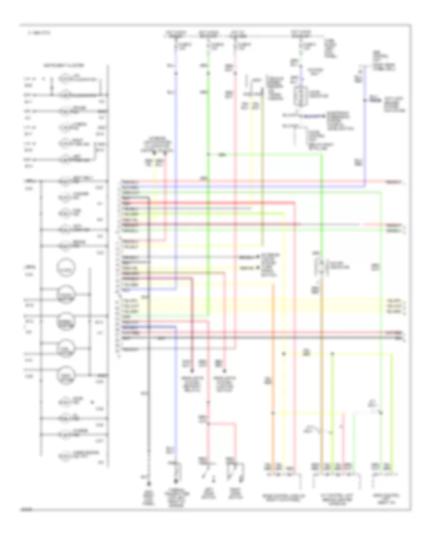
Instrument Cluster Wiring Diagram, without Head-Up Display (1 of 2) for Nissan 240SX SE 1994
List of elements for Instrument Cluster Wiring Diagram, without Head-Up Display (1 of 2) for Nissan 240SX SE 1994:
- (behind center console)
- (below right "b" pillar)
- (mil)
- (right rear wheelwell)
- 1995 vftc c
- A-1
- A-10
- A-2
- A-3
- A-4
- A-5
- A-6
- A-7
- A-8
- A-9
- A/t control unit
- A/t only
- Abs control unit
- Anti- lock ind.
- Anti-lock brakes system (actuator)
- Ascd control unit (right i/p)
- B-11
- B-12
- B-13
- B-14
- B-15
- B-16
- B-17
- B-18
- B-19
- B-20
- Bat
- Brake ind.
- C-21
- C-22
- C-23
- C-24
- C-25
- C-26
- C-27
- C-28
- C-30
- Charge ind.
- Check engine ind.
- Clock
- Cruise ind.
- Door ind.
- Eccs control module (right kick panel)
- Electronic suspension system (hicas oil level switch)
- Exterior lights system (turn signal switch)
- Fuel gauge
- Fuel ind.
- Fuse b 10a
- Fuse block (left kick panel)
- Fuse d 10a
- Fuse k 10a
- Fuse r 10a
- G203 (right kick panel)
- Gnd
- Headlights system (lighting switch)
- Headlights system (retract relay-2)
- Hi beam ind.
- Hicas control unit
- Hicas indicator
- Hot at all times
- Hot in run or acc
- Hot in run or start
- Ign
- Illumination
- Instrument cluster
- Interior lights system (illumination control switch)
- Lcd illumination
- Left door switch
- Left turn ind.
- Nca
- O/d off indicator
- Oil ind.
- Red
- Right door switch
- Right turn ind.
- Seat belt ind.
- Speed- ometer
- Tacho- ometer
- Temp. gauge
- Thermal transmitter (top left front of engine)
- Vehicle speed sensor (on trans- mission)
- W/hicas only
- Washer ind.
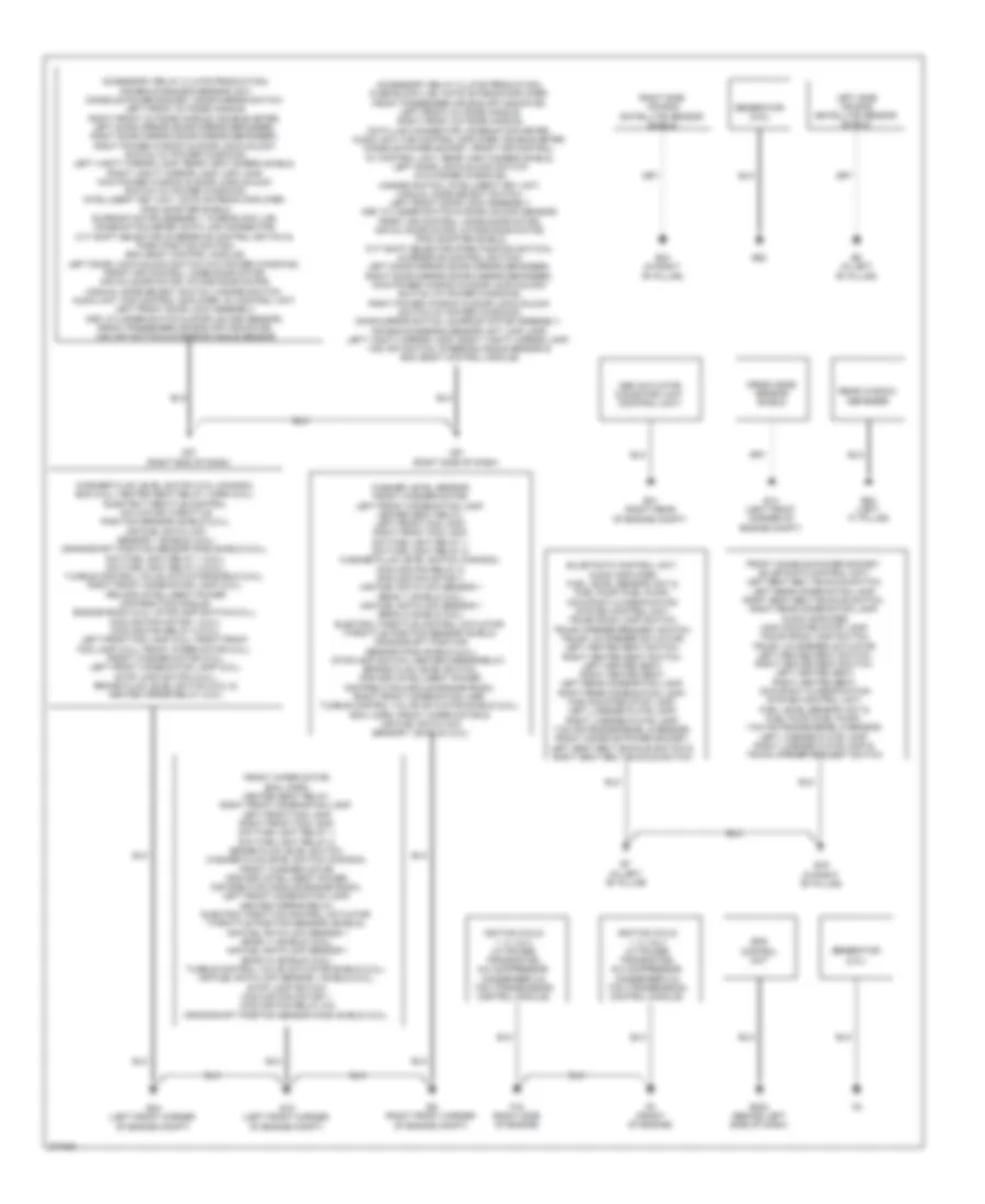
Instrument Cluster Wiring Diagram, without Head-Up Display (2 of 2) for Nissan 240SX SE 1994
List of elements for Instrument Cluster Wiring Diagram, without Head-Up Display (2 of 2) for Nissan 240SX SE 1994:
- Abs actuator & electric unit (control unit)
- Accessory relay 2 (late production), air bag diagnosis sensor unit, console power socket, door mirror switch, left front outside handle, right front outside handle, double meter, left door mirror (door mirror defogger), right door mirror (door mirror defogger), right power window & door lock/unlock switch (w/ power windows), left vanity mirror lamp, rear view camera shield, right vanity mirror lamp, map lamp, main power window & door lock/unlock switch (w/ power windows), intelligent key unit, nats antenna amplifier, ipod adapter shield, sunroof motor assembly, fuse block (j/b), combination meter, data link connector, cvt shift selector (overdrive control switch & park position switch), bcm (body control module), left door lock/unlock switch (w/o power windows), front air control, mode door motor, air mix door motor, intake door motor, manual mode select switch, hazard switch, audio unit, fan control amplifier, av control unit, left front door lock assembly (key cylinder switch & door unlock sensor), front passenger air bag off indicator, vdc off switch & steering angle sensor
- Accessory relay 2 (late production), fuse block (j/b), nats antenna amplifier, front passenger air bag off indicator, left front outside handle, right front outside handle, data link connector, combination meter, audio unit, fan control amplifier, double meter, console power socket, front air control, av control unit, rear view camera shield, left door lock/unlock switch (w/o power windows), hazard switch, intelligent key unit, manual mode select switch, left front door lock assembly (key cylinder switch & door unlock sensor) front air control, mode door motor, air mix door motor, intake door motor, ipod adapter shield, cvt shift selector (park postion switch), (overdrive control switch), left door mirror (door mirror defogger), right door mirror (door mirror defogger), main power window & door lock/unlock switch (w/ power windows), right power window & door lock/unlock switch (w/ power windows), door mirror switch, sunroof motor assembly, air bag diagnosis sensor unit, map lamp, left vanity mirror lamp, right vanity mirror lamp, vdc off switch, steering angle sensor & bcm (body control module)
- B19 (in right "b" pillar)
- B34 (in right "b" pillar)
- B5 (in left "b" pillar)
- B64 (left "c" pillar)
- B7 (in left "b" pillar)
- Crash zone sensor shield
- E14 (left front corner of engine compt)
- E15 (left front corner of engine compt)
- E203 (behind left side of dash)
- E24 (left front corner of engine compt)
- E41 (right rear of engine compt)
- E62
- E9 (right front corner of engine compt)
- Eps control unit
- F16 (right side of engine)
- F9 (front of engine)
- Front wiper motor, ecm, horn, heated seat relay, right front combination lamp, left front fog lamp, right front fog lamp, daytime light relay 1, daytime light relay 2, brake fluid level switch, washer fluid level switch (canada), front washer motor, ipdm e/r (intelligent power distribution module engine room), left front combination lamp, heated mirror relay, electric throttle control actuator (throttle position sensor) (shield), air fuel ratio (a/f) sensor 1 (bank 1) (shield) (2.5l), air fuel ratio (a/f) sensor 1 (bank 2) (shield) (2.5l), tumble control valve actuator shield (2.0l), air fuel ratio (a/f) sensor 1 shield (2.0l), stop lamp switch, cooling fan motor 1, cooling fan relay 5 & crankshaft position sensor (pos) shield (2.0l)
- Generator (2.0l)
- Generator (2.5l)
- Ignition coils 1, 2, 3 & 4 (w/ power transistor), a/c compressor, condenser 2 & tcm (transmission control module)
- Left side air bag (satellite) sensor shield
- M57 (right end of dash)
- M61 (right side of dash)
- Rear window defogger
- Right side air bag (satellite) sensor shield
- Washer fluid level switch (2.0l canada), ecm (2.0l), heated seat relay, horn (2.0l), electric throttle control actuator (throttle position sensor) shield (2.0l), air fuel ratio (a/f) sensor 1 (shield) (2.0l), crankshaft position sensor (pos) shield (2.0l), daytime light relay 1 (2.0l), daytime light relay 2 (2.0l), tumble control valve actuator shield (2.0l), right front combination lamp (2.0l), ipdm e/r (intelligent power distribution module, engine room) (2.0l), stoplamp switch (2.0l), cooling fan motor 1 (2.0l), cooling fan relay 5 (2.0l), left front fog lamp (2.0l), right front fog lamp (2.0l), front wiper motor (2.0l), front washer motor (2.0l), left front combination lamp (2.0l), stop lamp switch (2.0l), brake fluid level switch (2.0l) & heated mirror relay (2.0l)
- Washer level sensor, front washer motor, left front combination lamp, heated seat relay, left front fog lamp, right front fog lamp, daytime light relay 1, daytime light relay 2, washer fluid level switch (canada), cooling fan relay 5, cooling fan motor 1, air fuel ratio (a/f) sensor 1 (bank 1) shield (2.5l), air fuel ratio (a/f) sensor 1 (bank 2) shield (2.5l), electric throttle control actuator (throttle position sensor) shield, crankshaft position sensor (pos) shield (2.0l), stoplamp switch, heated mirror relay, brake fluid level switch, ipdm e/r (intelligent power distribution module engine room), right front combination lamp, tumble control valve actuator shield (2.0l), ecm, horn, front wiper motor & air fuel ratio (a/f) sensor 1 (shield) (2.0l)

 Čeština
 Dansk
Dansk Deutsch
 Ελληνικά
 English
 Español
 Suomi
Suomi Français
 Français
 עברית
עברית Hrvatski
 Magyar
 Italiano
 日本語
日本語 한국어
한국어 Nederlands
 Polski
 Português
 Português
 Română
 Русский
 Slovenčina
 Slovenščina
 Svenska
 Türkçe
 中文 (中国)