INTERIOR LIGHTS
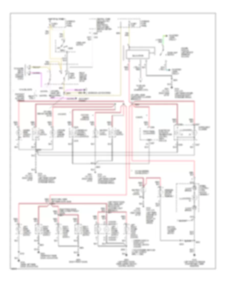
Courtesy Lamps Wiring Diagram for Mercury Mountaineer 1997
 https://portal-diagnostov.com/license.html
Automotive Electricians Portal FZCO
Automotive Electricians Portal FZCO
https://portal-diagnostov.com/license.html
https://portal-diagnostov.com/license.html
Automotive Electricians Portal FZCO
Automotive Electricians Portal FZCO
List of elements for Courtesy Lamps Wiring Diagram for Mercury Mountaineer 1997:
- (i/p harn, near left kick panel)
- Auxiliary relay box #4 (left rear of vehicle, above wheelwell)
- Bat saver rly ctrl
- Battery saver relay
- C280
- C283
- Cargo lamp
- Central timer module (ctm)/ generic electronic module (gem) (behind center of i/p)
- Compass/ outside air temperature module
- Dimmer module (left side of steering column)
- Dome lamp
- Dome lamp switch
- Fuse 27 10a
- Fuse 8 30a
- G104 (left rear corner of engine compartment, at fender apron)
- G200 (left kick panel)
- G412 (rear center of vehicle, in lifgate)
- G412 (rear of vehicle)
- G500 (left front door, near master window control switch)
- G600 (right front door)
- Glove box lamp and switch
- Hot at all times
- Int lamp rly ctrl
- Interior fuse panel
- Interior lamp relay
- Left front door ajar switch
- Left front door courtesy lamp
- Left liftgate ajar switch
- Left rear door ajar switch
- Left vanity mirror lamp/switch
- Lf door ajar input
- Liftgate disable/ajar
- Liftgate wiper disable switch (w/ power equipment group)
- Lr door ajar input
- Map lamp
- Nca
- Pnk
- Power distribution box
- Rear dome lamp
- Rear map lamp
- Relay module (behind center of i/p)
- Rf door ajar input
- Right front door ajar switch
- Right front door courtesy lamp
- Right liftgate ajar switch
- Right rear door ajar switch
- Right vanity mirror lamp/switch
- Rr door ajar input
- S104
- S203
- S234
- S238
- S246
- S302
- S322
- S407
- S500
- S602
- Underhood lamp
- W/ overhead console only
- W/ power equipment group
- W/o overhead console only
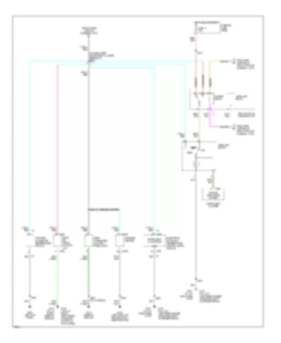
Instrument Illumination Wiring Diagram (1 of 2) for Mercury Mountaineer 1997
List of elements for Instrument Illumination Wiring Diagram (1 of 2) for Mercury Mountaineer 1997:
- (2-door)** (4-door)
- (3)
- (4-door) (2-door)**
- (i/p harn, near instrument cluster breakout)
- (i/p harn, behind center of i/p)
- (i/p harn, near left kick panel) s267
- (left front door harn, near left front door courtesy lamp breakout) s501
- (left rear corner of engine compt, at fender apron)
- (right side of i/p)
- ** mountaineer vehicles w/ job 1 date of april 1, 1996)
- 4x4 mode switch
- Anti-theft system
- Ashtray illum- ination
- C276
- C280
- C286
- C287
- C297
- C298
- Central timer module (ctm)/ generic electronic module (gem) (behind center of i/p)
- Clock spring
- Courtesy lamps circuit
- Day/night mirror/ autolamp sensor
- Dimmer module (left side of steering column)
- Dome lamp switch
- Door) s601
- Electronic automatic temperature control (eatc) module
- Exterior lights system
- Fog lamp switch
- Front panel illumination
- Fuse 3 15a
- Fuse 7 7.5a
- G100 (left front of engine compartment, near radiator)
- G104 (w/o lux)
- G201 (w/ lux)
- G500 (left front door, near master window control switch)
- G600 (right front door)
- G700 (near left rear door lock motor)
- G800 (near right rear door lock motor)
- Gnd
- Head
- Headlamp switch
- Heated rear window switch
- Heater-a/c control assembly illumination
- Hot at all times
- Ignition cylinder tamper switch
- Illumination
- Illumination (2)
- Instrument cluster
- Interior fuse panel
- Left front power door lock switch (2-door)
- Left front power window switch
- Left rear power window switch
- Liftgate wiper/ washer switch
- Master window/ * door lock control switch (4-door)
- Message center switch assembly
- Nca
- Off
- Park
- Park lamp relay
- Red/ (body harn, near left rear door jamb) s240
- Relay ctrl
- Relay module (behind center of i/p)
- Right front power door lock switch
- Right front power window switch
- Right rear power window switch
- S200
- S229
- S230
- S232
- S233
- S244
- S264
- S500
- S602
- S700
- S800
- Solid state
- Speed control/ horn switch assembly
- To dimmer relay (relay module) (diagram 2 of 2)
- To splice s228 (diagram 2 0f 2)
- W/ autolamps
- W/ eatc
- W/ high series console only
- W/o eatc
- W/o high series console
Instrument Illumination Wiring Diagram (2 of 2) for Mercury Mountaineer 1997
List of elements for Instrument Illumination Wiring Diagram (2 of 2) for Mercury Mountaineer 1997:
- (diagram 1 of 2)
- (i/p harn, near instrument cluster breakout) s228
- C2008
- C2009
- C228
- C286
- C297
- C298
- Compass/ outside air temperature module
- Dimmer relay
- Dimming indicators (power)
- Electronic automatic temperature control (eatc) module
- From dimmer module (diagram 1 of 2)
- From park lamp relay (relay module)
- From park lamp relay (relay module) (diagram 1 of 2)
- Fuse 11 7.5a
- G100 (left front of engine compt, near radiator)
- G104 (w/o lux) (left rear corner of engine compt, at fender apron)
- G105 (w/o lux radio) (right rear of engine compt, on cowl panel)
- G200 (left kick panel)
- G201 (w/ lux (right side of i/p)
- G412 (rear of vehicle)
- G412 (w/ lux radio) (rear of vehicle)
- Gnd
- Head
- Headlamp relay
- Headlamp switch
- Hot in run or start
- Instrument cluster
- Instrument illumination
- Interior fuse panel
- Message center
- Off
- Park
- Radio or front control unit
- Rear integrated control panel (ricp)
- Relay module (center of i/p)
- S200
- S202
- S208 (w/ message center)
- S213
- S230
- S233
- S252 (w/ lux radio)

 Čeština
 Dansk
Dansk Deutsch
 Ελληνικά
 English
 English
 Español
 Suomi
Suomi Français
 Français
 עברית
עברית Hrvatski
 Magyar
 Italiano
 日本語
日本語 한국어
한국어 Nederlands
 Polski
 Português
 Português
 Română
 Русский
 Slovenčina
 Slovenščina
 Türkçe
 中文 (中国)