MEMORY SYSTEMS
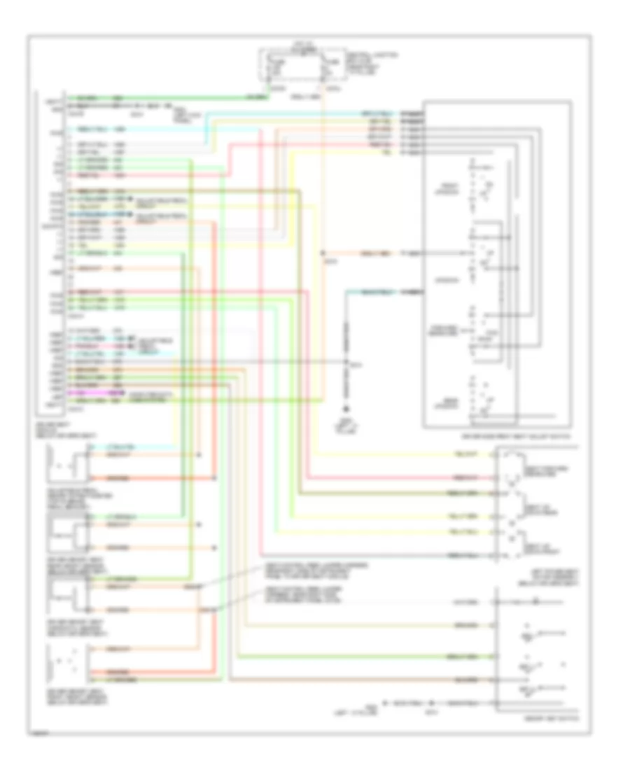
Adjustable Pedal Wiring Diagram for Ford Pickup F350 Super Duty 2004
 https://portal-diagnostov.com/license.html
Automotive Electricians Portal FZCO
Automotive Electricians Portal FZCO
https://portal-diagnostov.com/license.html
https://portal-diagnostov.com/license.html
Automotive Electricians Portal FZCO
Automotive Electricians Portal FZCO
List of elements for Adjustable Pedal Wiring Diagram for Ford Pickup F350 Super Duty 2004:
- (seat control feed jumper harness, near right side of instrument panel c3135)
- (seat control feed jumper harness, near right side of instrument panel to driver seat module)
- Adjustable pedal memory potentiometer (top of brake pedal bracket)
- Adjustable pedal motor (behind lower left side of dash)
- Adjustable pedal switch
- C270m
- C341a
- C341b
- C341c
- Central junction box (cjb) (near right ``a" pillar)
- Computer data lines system
- Driver seat module (below driver's seat)
- Driver's memory seats circuit
- Forward
- Fuse 30a
- G200 (left ``a" pillar)
- G202 (in left front footwell)
- G303 (left kick panel)
- Gnd
- Hot at all times
- Interior lights system
- Nca
- Pwr
- Rearward
- Rest
- S205
- S208
- S301
- S302
- S310
- Sig
- Sig rtn
- Ubp
- Vbatt
- Vref
Driver"s Memory Seat Wiring Diagram for Ford Pickup F350 Super Duty 2004
List of elements for Driver"s Memory Seat Wiring Diagram for Ford Pickup F350 Super Duty 2004:
- (seat control feed jumper harness, near right side of instrument panel c3135)
- (seat control feed jumper harness, near right side of instrument panel to driver seat module)
- +/-
- Adjustable pedal circuit
- Adjustable pedal memory potentiometer (top of brake pedal bracket)
- C270j
- C270m
- C341a
- C341b
- C341c
- Central junction box (cjb) (near right ``a" pillar)
- Computer data lines system
- Driver memory seat front height sensor (below driver's seat)
- Driver memory seat horizontal sensor (below driver's seat)
- Driver memory seat rear height sensor (below driver's seat)
- Driver seat module (below driver's seat)
- Driver side front seat adjust switch
- Forward/ rearward
- Front up/down
- Fuse 30a
- Fuse 5a
- Fwd
- G200 (left ``a" pillar)
- G303 (left kick panel)
- Gnd
- Hot at all times
- Left power seat motor assembly (below driver's seat)
- Memory set switch
- Nca
- Pwr
- Rear up/down
- Rwd
- S301
- S302
- S310
- S314
- S315
- Seat forward/ rearward
- Seat up/ down front
- Seat up/ down rear
- Set
- Set 1
- Set 2
- Sig
- Sig rtn
- Ubp
- Up/down
- Vbatt
- Vref

 Čeština
 Dansk
Dansk Deutsch
 Ελληνικά
 English
 Español
 Suomi
Suomi Français
 Français
 עברית
עברית Hrvatski
 Magyar
 Italiano
 日本語
日本語 한국어
한국어 Nederlands
 Polski
 Português
 Português
 Română
 Русский
 Slovenčina
 Slovenščina
 Svenska
 Türkçe
 中文 (中国)