NAVIGATION
Crew Chief Wiring Diagram for Ford Transit Connect XL 2014
 https://portal-diagnostov.com/license.html
Automotive Electricians Portal FZCO
Automotive Electricians Portal FZCO
https://portal-diagnostov.com/license.html
https://portal-diagnostov.com/license.html
Automotive Electricians Portal FZCO
Automotive Electricians Portal FZCO
List of elements for Crew Chief Wiring Diagram for Ford Transit Connect XL 2014:
- 5vpwr
- 5vtb
- Body control module (bcm) (behind right center of dash)
- C2280e
- C2280f
- Cgnd
- Computer data lines system
- Fuse 10a
- Fuse 7.5a
- G204 (left end of dash)
- Gnd
- Gnd2
- Hot at all times
- Hot in run or start
- Hs can+
- Hs can-
- Hscanm
- Hscanp
- Ignrs
- Inline fuse (left side of dash)
- Modem antenna (lower center of dash)
- Nca
- Nca 5vpwr
- Nca gnd
- Nca rxd
- Pwr gnd
- Red
- Run/ start
- Rxd
- S260
- S261
- S262
- Telematics module (left end of dash)
- Txd
- Vb1
- Vbatt
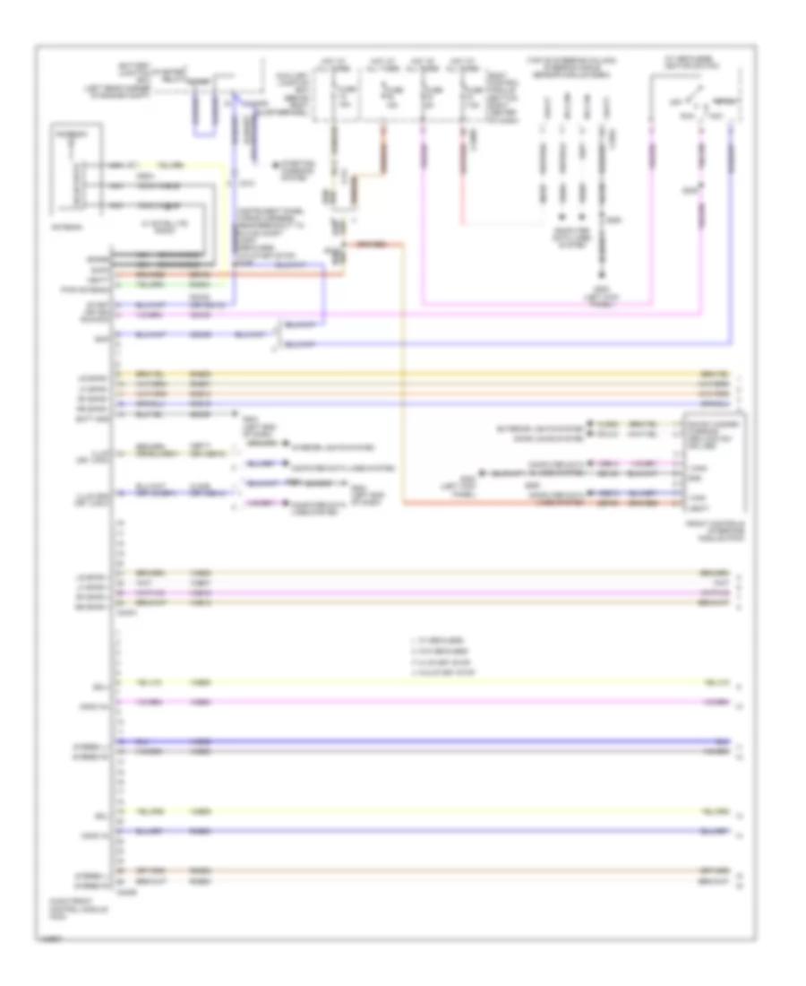
Navigation Wiring Diagram, with SYNC GEN 1 (1 of 3) for Ford Transit Connect XL 2014
List of elements for Navigation Wiring Diagram, with SYNC GEN 1 (1 of 3) for Ford Transit Connect XL 2014:
- (instrument panel wiring harness, near breakout to glove compt lamp) (mechless w/o start/stop) s249
- (top of steering column) steering angle sensor module (sasm)
- (w/ mechless)
- Acc
- Air bag off
- Air bag on
- Am/fm
- Antenna
- Audio front control module (acm)
- Auxiliary junction box (behind right quarterpanel)
- Batt gnd
- Battery junction box (bjb) (left rear corner of engine compt)
- Body control module (bottom right center of dash)
- C1035c
- C212
- C226a
- C2280f
- C240a
- C240b
- C311
- C9021
- Cbp17 (or vdb13)
- Cbp86
- Cdc33
- Cdc35
- Cdc35 (or cdc12)
- Cln29 (or vdb14)
- Cme44
- Coax cable
- Computer data lines system
- Cr114
- Cr116
- Front controls interface module (fcim)
- Fuse 10a
- Fuse 15a
- Fuse 5a
- Fuse 7.5a
- G202 (left kick panel)
- G204 (left end of dash)
- Gd133
- Gd138
- Gd339
- Gnd
- Hot at all times
- Hot in run or start
- Hs can+
- Hs can-
- Ign
- Ignition switch
- Illum (or i can-)
- Illum gnd (or i can+)
- Interior lights system
- Iscp
- Lf spkr +
- Lf spkr -
- Lin
- Lr spkr +
- Lr spkr -
- Mono in+
- Mono in-
- Nca
- Off
- Pwr antenna
- Red
- Rf spkr +
- Rf spkr -
- Rme07
- Rme09
- Rme10
- Rme12
- Rme17
- Rme18
- Rme80
- Rr spkr +
- Rr spkr -
- Run
- Run/acc
- S223
- S235
- S239
- S250
- Sbp06
- Sbp07
- Sdars
- Solid state
- Start
- Start (or ign)
- Starter relay start
- Starting/ charging system
- Stereo l+
- Stereo l-
- Stereo r+
- Stereo r-
- Vbatt
- Vdb04
- Vdb05
- Vmc29
- Vme07
- Vme09
- Vme10
- Vme12
- Vme17
- Vme18
- Vme80
- W/ mechless
- W/ satellite radio
- W/ start stop
- W/o mechless
- W/o start stop
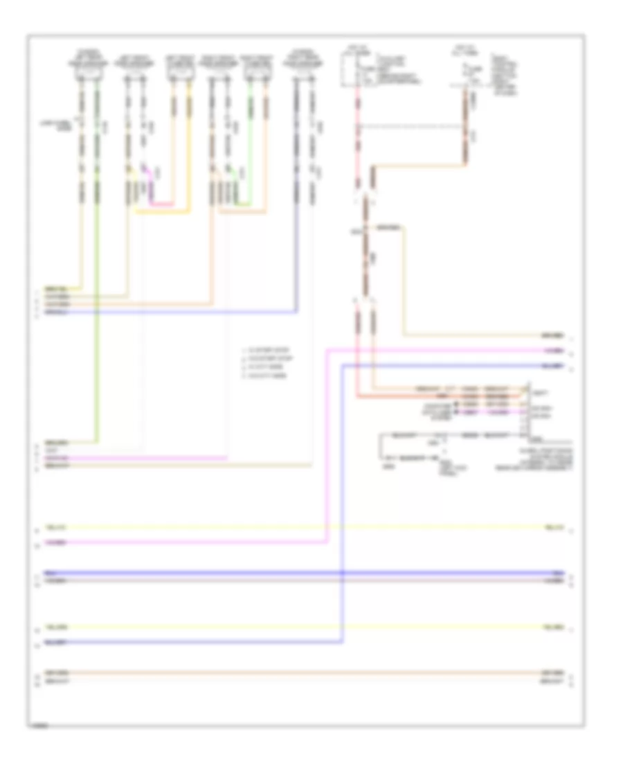
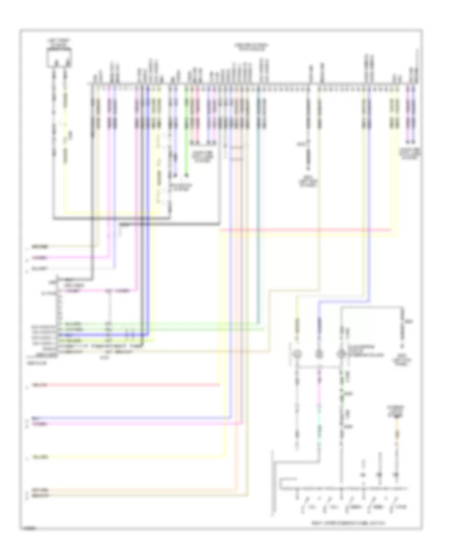
Navigation Wiring Diagram, with SYNC GEN 1 (2 of 3) for Ford Transit Connect XL 2014
List of elements for Navigation Wiring Diagram, with SYNC GEN 1 (2 of 3) for Ford Transit Connect XL 2014:
- (left end of dash) g204
- (wagon) left rear door speaker
- (wagon) right rear door speaker
- All times
- Audio anti-theft switch
- Audio remote+
- Audio remote-
- Auxiliary junction box (behind right quarterpanel)
- Body control module (bottom right center of dash)
- C2280c
- C2280e
- C311
- C510
- C610
- C710
- C810
- C900
- C991
- Computer data lines system
- Computer data lines system navigation system
- Front control/ display interface module (fcdim)
- Fuse 7.5a
- G202 (left kick panel)
- G204 (left end of dash)
- Gd138
- Gd338
- Global positioning system module (integral to inside rearview mirror assembly)
- Gnd
- Hot at all times
- I can+
- I can-
- Left front door speaker
- Left front tweeter
- Lin
- Long wheel base
- Micro
- Ms can+
- Ms can-
- Navigation system
- Red
- Right front door speaker
- Right front tweeter
- Rme24
- Rmp31
- S234
- S906
- Sbp06
- Vbatt
- Vdb06
- Vdb07
- Vdb13
- Vdb14
- Video+
- Video-
- Vmc29
- Vme14
- Vmn03
- Vmp19
- Vmp31
- W/ city safe
- W/ start stop
- W/o city safe
- W/o start stop
Navigation Wiring Diagram, with SYNC GEN 1 (3 of 3) for Ford Transit Connect XL 2014
List of elements for Navigation Wiring Diagram, with SYNC GEN 1 (3 of 3) for Ford Transit Connect XL 2014:
- (center of dash) sync module
- (left front of roof) microphone
- Audio input socket
- C218a
- C218b
- C260
- C900
- C935
- Clockspring (top of steering column)
- Computer data lines system
- Dme17
- Dme37
- Dme80
- Dmm13
- G202 (left kick panel)
- G204 (left end of dash)
- Gd135
- Gnd
- Hs can+
- Hs can-
- I can+
- I can-
- Interior lights system
- L in
- L out
- Mic+
- Mic-
- Mono out +
- Mono out -
- Nca
- Pwr gnd
- R in
- R out
- Right upper steering wheel switch
- Rme17
- Rme18
- Rme45
- Rme80
- S233
- S243 (instrument panel wiring harness, near breakout to defrost mode door actuator)
- S250
- S255
- S256
- Sbp67
- Seek+
- Seek-
- Shield
- Stereo l+
- Stereo l-
- Stereo r+
- Stereo r-
- Usb
- Usb cable
- Usb port
- Vbatt
- Vdb04
- Vdb05
- Vdb13
- Vdb14
- Vme17
- Vme18
- Vme37
- Vme38
- Vme80
- Vmm13
- Voice
- Vol+
- Vol-
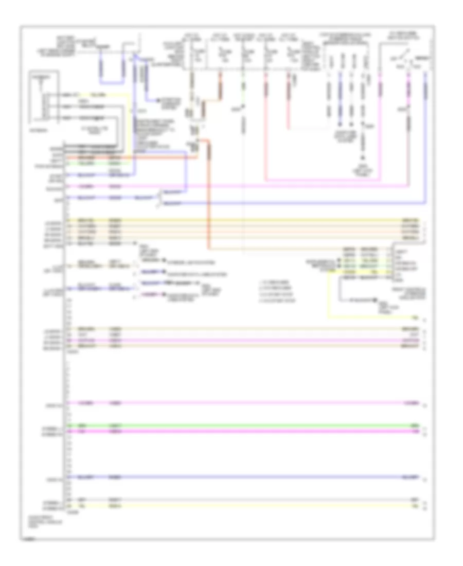
Navigation Wiring Diagram, with SYNC GEN 2 (1 of 3) for Ford Transit Connect XL 2014
List of elements for Navigation Wiring Diagram, with SYNC GEN 2 (1 of 3) for Ford Transit Connect XL 2014:
- (or i can-)
- (top of steering column) steering angle sensor module (sasm)
- (w/ mechless) ignition switch
- Acc
- Am/fm
- Antenna
- Audio front control module (acm)
- Auxiliary junction box (behind right quarterpanel)
- Batt gnd
- Battery junction box (left rear corner of engine compt)
- Body control module (bottom right center of dash)
- C1035c
- C212
- C226a
- C2280f
- C240a
- C240b
- C311
- C9021
- Cbp17 (or vdb13)
- Cdc33
- Cdc35
- Cdc35 (or cdc12)
- Cln29 (or vdb14)
- Cls32
- Cme44
- Coax cable
- Computer data lines system
- Cplxx
- Door locks system
- Exterior lights system
- Front controls interface module (fcim)
- Fuse 15a
- Fuse 5a
- Fuse 7.5a
- G202 (left kick panel)
- G204 (left end of dash)
- Gd133
- Gd138
- Gd339
- Glove compt lamp) (mechless w/o start/stop) s249
- Gnd
- Hot at all times
- Hs can+
- Hs can-
- I can+
- I can-
- Illum
- Illum gnd (or i can+)
- Interior lights system
- Iscp
- Lf spkr +
- Lf spkr -
- Lr spkr +
- Lr spkr -
- Mono in+
- Mono in-
- Nca
- Off
- Pwr antenna
- Red
- Rf spkr +
- Rf spkr -
- Rme07
- Rme09
- Rme10
- Rme12
- Rme52
- Rme53
- Rme80
- Rr spkr +
- Rr spkr -
- Run
- Run/acc
- S215 red
- S223
- S235
- S250
- Sbp06
- Sbp07
- Sdars
- Sdl+
- Sdl-
- Sig sw hazard warning cen lock sw ind (led)
- Solid state
- Start
- Start (or ign)
- Starter relay start
- Starting/ charging system
- Stereo l+
- Stereo l-
- Stereo r+
- Stereo r-
- Vbatt
- Vdb04
- Vdb05
- Vdb13
- Vdb14
- Vme07
- Vme09
- Vme10
- Vme12
- Vme52
- Vme53
- Vme58
- Vme59
- Vme80
- W/ mechless
- W/ satellite radio
- W/ start stop
- W/o mechless
- W/o start stop
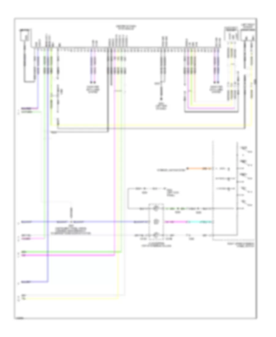
Navigation Wiring Diagram, with SYNC GEN 2 (2 of 3) for Ford Transit Connect XL 2014
List of elements for Navigation Wiring Diagram, with SYNC GEN 2 (2 of 3) for Ford Transit Connect XL 2014:
- (wagon) left rear door speaker
- (wagon) right rear door speaker
- Auxiliary junction box (behind right quarterpanel)
- Body control module (bottom right center of dash)
- C2280e
- C311
- C510
- C610
- C710
- C810
- C900
- C991
- Computer data lines system
- Fuse 7.5a
- G202 (left kick panel)
- Gd338
- Global positioning system module (integral to inside rearview mirror assembly)
- Gnd
- Hot at all times
- Left front door speaker
- Left front tweeter
- Long wheel base
- Ms can+
- Ms can-
- Red
- Right front door speaker
- Right front tweeter
- S906
- Vbatt
- Vdb06
- Vdb07
- Vmn03
- W/ city safe
- W/ start stop
- W/o city safe
- W/o start stop
Navigation Wiring Diagram, with SYNC GEN 2 (3 of 3) for Ford Transit Connect XL 2014
List of elements for Navigation Wiring Diagram, with SYNC GEN 2 (3 of 3) for Ford Transit Connect XL 2014:
- (center of dash) sync module
- (left front of roof) microphone
- 5v pwr
- Audio remote+
- Audio remote-
- Aux audio l+
- Aux audio l-
- Aux audio r+
- Aux audio r-
- C218a
- C218b
- C260
- C315
- C900
- C935
- Clockspring (top of steering column)
- Computer data lines system
- Dme45
- Dme52
- Dme80
- Dmm13
- G202 (left kick panel)
- G204 (left end of dash)
- Gd338
- Hs can+
- Hs can-
- I can+
- I can-
- Interior lights system
- Media gnd
- Media hub
- Mic+
- Mic-
- Mono out +
- Mono out -
- Ms can+
- Ms can-
- Navigation system
- Nca
- Pwr gnd
- Right upper steering wheel switch
- Rme24
- Rme45
- Rme46
- Rme52
- Rme53
- Rme67
- Rme80
- Rmp31
- S233
- S250
- S255
- S256
- Sbp06
- Sdl+
- Sdl-
- Seek+
- Seek-
- Shield
- Stereo l+
- Stereo l-
- Stereo r+
- Stereo r-
- Usb
- Usb cable
- Vbatt
- Vdb04
- Vdb05
- Vdb06
- Vdb07
- Vdb13
- Vdb14
- Video+
- Video-
- Vme14
- Vme45
- Vme46
- Vme52
- Vme53
- Vme58
- Vme59
- Vme67
- Vme80
- Vmm13
- Vmp31
- Voice
- Vol+
- Vol-
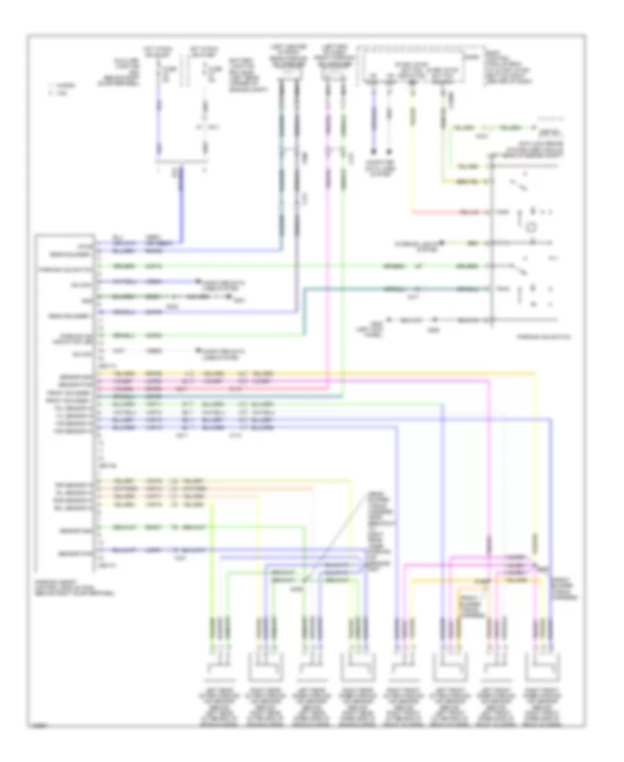
Parking Assistant Wiring Diagram for Ford Transit Connect XL 2014
List of elements for Parking Assistant Wiring Diagram for Ford Transit Connect XL 2014:
- (front bumper wiring harness)
- (left center of roof) rear parking aid speaker
- (left end of dash) front parking aid speaker
- (rear bumper wiring harness, near breakout to right rear inner parking aid sensor) s407
- Anti-lock brake system (abs) module (left rear of engine compt)
- Auxiliary junction box (behind right quarterpanel)
- Battery junction box (bjb) (left rear corner of engine compt)
- Body control module (bcm) (w/ start stop) (bottom right center of dash)
- C110
- C211
- C212
- C2280c
- C311
- C431
- C900
- C9071a
- C9071b
- C9071c
- Cbr01 (or cbb37)
- Cmp02
- Cmp08
- Cmp09
- Cmp18
- Computer data lines system
- Esp-sw
- Fil sensor in
- Fir sensor in
- Fol sensor in
- For sensor in
- Front sounder +
- Front sounder -
- Fuse 5a
- G202 (left kick panel)
- G401
- Gd351
- Gnd
- Hot in run or start
- Hs can+
- Hs can-
- Interior lights system
- Left front inner parking aid sensor (behind left front inner side of front bumper)
- Left front outer parking aid sensor (behind left front outer end of front bumper)
- Left rear inner parking aid sensor (behind left rear inner side of rear bumper)
- Left rear outer parking aid sensor (behind left rear outer end of rear bumper)
- Lmp06
- Lmp07
- Micro
- Nca
- Parking aid indication led
- Parking aid switch
- Parking assist control module (pam) (behind right quarterpanel)
- Rear sounder +
- Rear sounder -
- Right front inner parking aid sensor (behind right front inner side of front bumper)
- Right front outer parking aid sensor (behind right front outer end of front bumper)
- Right rear inner parking aid sensor (behind right rear inner side of rear bumper)
- Right rear outer parking aid sensor (behind right rear outer end of rear bumper)
- Ril sensor in
- Rir sensor in
- Rmp06
- Rmp07
- Rmp08
- Rmp09
- Rol sensor in
- Ror sensor in
- S195
- S196
- S250
- S402
- S406
- Sensor gnd
- Sensor pwr
- Start stop button indication led
- Start stop button switch
- Van
- Vdb04
- Vdb05
- Vmp10
- Vmp11
- Vmp12
- Vmp13
- Vmp14
- Vmp15
- Vmp16
- Vmp17
- Vpwr
- Wagon
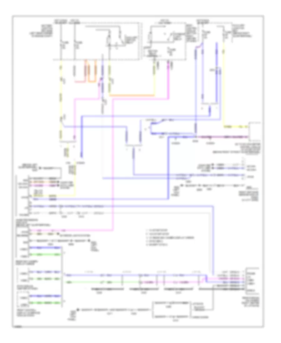
Rear Camera Wiring Diagram for Ford Transit Connect XL 2014
List of elements for Rear Camera Wiring Diagram for Ford Transit Connect XL 2014:
- (behind left quarterpanel) g400
- Auxiliary ignition relay
- Auxiliary junction box (behind right quarterpanel)
- Battery junction box (bjb) (left rear corner of engine compt)
- Body control module (bottom right center of dash)
- C211
- C2280b
- C2280h
- C311
- C339
- C410
- C423
- C495
- C900
- C934
- C991
- Cargo doors
- Cbr11
- Cbr99
- Cmf01
- Cmp10
- Computer data lines system
- Cyd05
- Dc to dc converter control module (w/ start-stop) (behind front of right quarterpanel)
- Except sync 2
- Exterior lights system
- Front control/ display interface module (fcdim)
- Front distance sensing module (fdsm) (w/ city safe)
- Fuse 5a
- G202 (left kick panel)
- Gd113
- Gd349
- Gnd
- Hot at all times
- Hot in run or start
- Hs can+
- Hs can-
- Ignition relay control
- Image processing module b (behind left quarterpanel)
- Interior light relay
- Liftgate
- Lin
- Micro
- Ms can+
- Ms can-
- Nca
- Power
- Rear parking aid camera (right center of liftgate)
- Rearview camera display mirror
- Reverse
- Rmp31
- S331
- S346
- S906
- Shield
- Smp22
- Sync gen 2
- Sync module (center of dash)
- Van
- Vdb04
- Vdb05
- Vdb06
- Vdb07
- Video+
- Video-
- Vmp31
- Vmp35
- Vpwr
- W/ rearview camera display mirror
- W/ start-stop
- W/o start-stop
- Wagon

 Čeština
 Dansk
Dansk Deutsch
 Ελληνικά
 English
 Español
 Suomi
Suomi Français
 Français
 עברית
עברית Hrvatski
 Magyar
 Italiano
 日本語
日本語 한국어
한국어 Nederlands
 Polski
 Português
 Português
 Română
 Русский
 Slovenčina
 Slovenščina
 Svenska
 Türkçe
 中文 (中国)