NAVIGATION
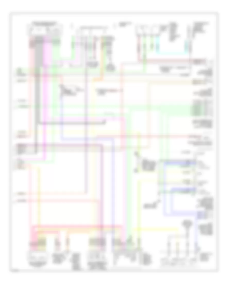
Navigation Wiring Diagram (1 of 2) for Infiniti Q45 2003
 https://portal-diagnostov.com/license.html
Automotive Electricians Portal FZCO
Automotive Electricians Portal FZCO
https://portal-diagnostov.com/license.html
https://portal-diagnostov.com/license.html
Automotive Electricians Portal FZCO
Automotive Electricians Portal FZCO
List of elements for Navigation Wiring Diagram (1 of 2) for Infiniti Q45 2003:
- (not used pins are not shown)
- 12r
- 17d
- 19b
- 19d
- 20b
- 23r
- 26r
- A/c auto amplifier (behind right side of dash)
- A/c-av(fr tx)
- Ac-av
- Acc
- Acclk
- Av & navi control unit (under left side of rear parcel shelf)
- Av-a/c(fr rx)
- Av-ac
- Av-cn
- Av-me
- B188
- B231
- B233
- B234
- B29
- B30
- B57 (at center rear of vehicle)
- Bat
- Bose speaker amplifier (at center front of trunk)
- Bus shield
- Bus+
- Bus-
- Clk (fr)
- Cn-av
- Comm sig +
- Comm sig -
- Display
- E201
- E24 (on right front strut tower)
- Exterior lights system
- Fr-sp lh +
- Fr-sp lh -
- Fuse 10a
- Fuse 15a
- Fuse block (j/b) 1 (behind left end of dash)
- Fuse, fusible link & relay block (j/b) (in engine room box)
- Gnd
- Gps ant gnd
- Gps antenna
- Gps sig
- Hot at all times
- Hot in acc or on
- Hot in on or start
- Ign
- Ill
- Instrument cluster system (voice activated control module)
- Joint connector 12 (behind top center of dash, taped to harness)
- Joint connector 3 (behind upper left side of dash)
- Joint connector 4 (behind upper left of dash)
- Left front door speaker
- M114 (behind right side of dash)
- Me-av
- Multi- function switch
- Navi +
- Navi -
- Nca
- Pnk
- Red
- Rgb gnd
- Rgb sync
- Shield
- Solid state
- Sound systems
- Speed
- Stoplight switch (on bracket, above brake pedal)
- Tail lamp relay
- Voice +
- Voice -
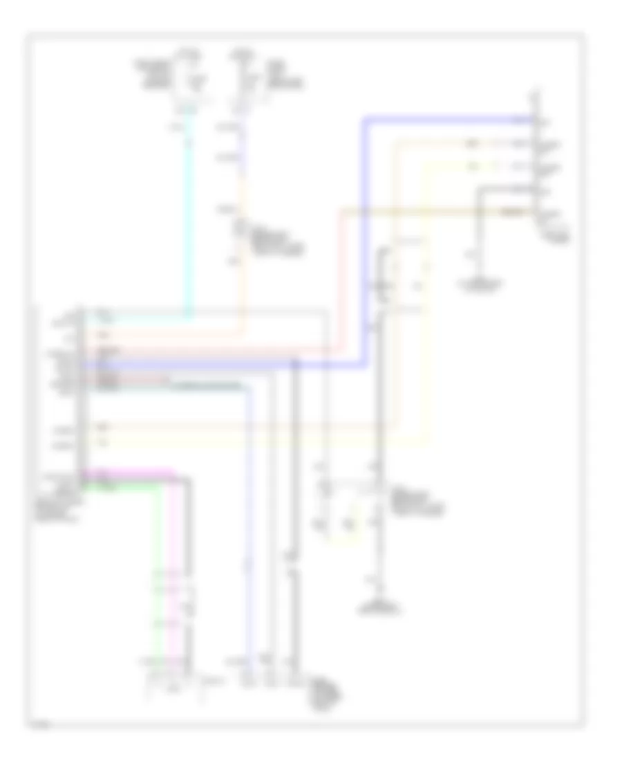
Navigation Wiring Diagram (2 of 2) for Infiniti Q45 2003
List of elements for Navigation Wiring Diagram (2 of 2) for Infiniti Q45 2003:
- (behind center of dash) joint connector 7
- (behind right side of dash) m115
- 1st
- 2nd
- A/t device
- Auto
- Backup lamp relay
- Bat
- Body control module (behind left kick panel)
- Comb sw
- Combination meter
- Combination switch (lighting module)
- Computer data lines system
- Data link connector (under left side of dash)
- Engine control module (behind glove box)
- Exterior lights system
- F101
- Fuse, fusible link & relay block (j/b) (in engine room box)
- Gnd1
- Gnd2
- Headlamp battery saver control uint (behind dash left of steering column)
- Ign sw
- Iiurx
- Iiutx
- Ill out
- Joint connector 11 (behind upper right side of dash, taped to harness)
- Joint connector 16 (behind upper right end of dash, taped to harness)
- Joint connector 17 (behind upper right end of dash, taped to harness)
- Joint connector 18 (behind upper right end of dash, taped to harness)
- Joint connector 3 (behind upper left side of dash)
- Joint connector 8 (behind center of dash)
- Joint connector 9 (behind center of dash)
- Lap output
- M24 (behind left side of dash)
- M25 (behind left side of dash)
- M33
- M34
- M41
- M43
- M55
- Nca
- Neut
- Off
- Parking brake switch (behind dash, at park brake assembly)
- Pnk
- Rap input
- Rev lamp rly
- Shieft lock solenoid
- Shift lk sol
- Start rly
- Starting/ charging system
- T/l rly out1
- T/l rly out2
- T/l sw1
- T/l sw2
- Tail/l rly
- Transmission control module (behind glove box)
- Unified meter control unit
Rear Camera Wiring Diagram for Infiniti Q45 2003
List of elements for Rear Camera Wiring Diagram for Infiniti Q45 2003:
- (behind left end of dash)
- (in engine room box)
- 23r
- Acc
- B217 (under right front door sill)
- B57 (at center rear of vehicle)
- Back up
- Bose speaker amplifier (at center front of trunk)
- Bus(+)
- Bus(-)
- Camera
- Camera on
- Camera+
- Camera-
- Compo sync
- Compo+
- Compo-
- Display
- Exterior lights system
- Fuse 10a
- Fuse 15a
- Fuse block (j/b) 1
- Fuse, fusible link & relay box (j/b)
- Gnd
- Hot at all times
- Hot in acc or on
- Iris
- Iris sw
- Joint connector 36 (behind right
- Joint connector 37 (behind right
- Nca
- Rear shock tower,
- Rear view camera
- Rear view camera control unit (at center front of trunk)
- Reverse
- Shield
- Sig+
- Sig-
- Sync
- Taped to harness)
- Tv+
- Tv-

 Čeština
 Dansk
Dansk Deutsch
 Ελληνικά
 English
 Español
 Suomi
Suomi Français
 Français
 עברית
עברית Hrvatski
 Magyar
 Italiano
 日本語
日本語 한국어
한국어 Nederlands
 Polski
 Português
 Português
 Română
 Русский
 Slovenčina
 Slovenščina
 Svenska
 Türkçe
 中文 (中国)