POWER DISTRIBUTION
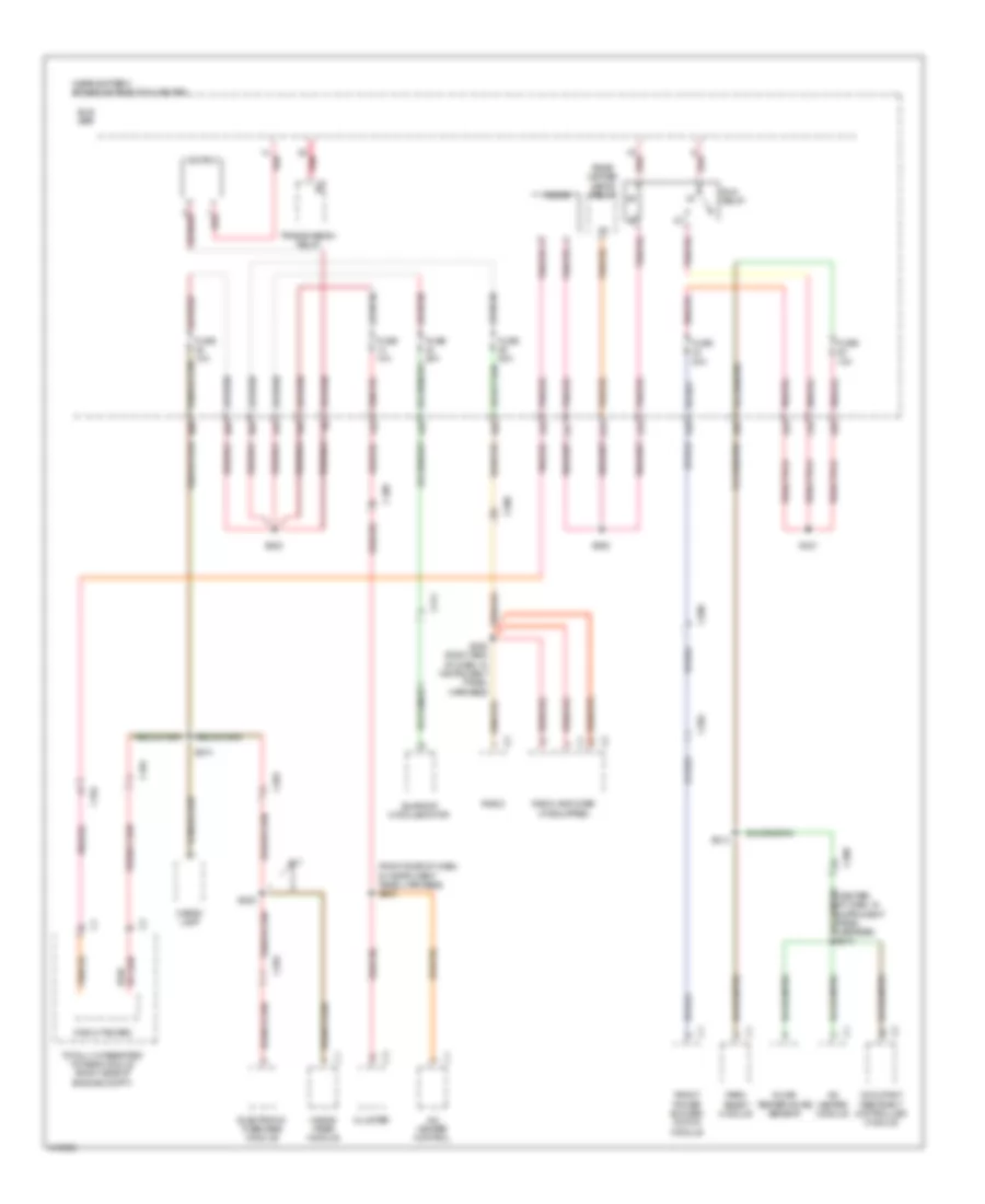
Power Distribution Wiring Diagram (1 of 4) for Dodge Challenger SXT Plus 2013
 https://portal-diagnostov.com/license.html
Automotive Electricians Portal FZCO
Automotive Electricians Portal FZCO
https://portal-diagnostov.com/license.html
https://portal-diagnostov.com/license.html
Automotive Electricians Portal FZCO
Automotive Electricians Portal FZCO
List of elements for Power Distribution Wiring Diagram (1 of 4) for Dodge Challenger SXT Plus 2013:
- (center of dash, in instrument panel harness) s201
- (near battery) power distribution center
- (not used)
- (right side of engine compt) totally integrated power module
- 10a
- 11a
- 16b
- 25a
- 30a
- 30b
- 33b
- 47a
- 47c
- 6.4l
- Anti-lock brakes module
- Auto shut down relay
- Bar
- Battery
- Bus
- C104
- C111
- C200
- Circuit breaker 11
- Cluster
- Console power outlet
- Diode 2
- Driver lumbar seat adjuster switch
- Driver seat switch
- Except 6.4l
- Front washer pump relay
- Fsd b(+)
- Fuse 10a
- Fuse 15a
- Fuse 20a
- Fuse 25a
- Fuse 25a red
- Fuse 30a
- Fuse 40a
- Fuse 50a tan/red
- G12a (under driver's seat)
- Generator
- Gnd
- I460a
- Nca
- Pass through post
- Power steering pump motor
- Powertrain control module
- Radiator fan 1 high/low relay
- Radiator fan 2 series/parallel relay
- Radiator fan 3 medium/high
- Red
- Red s138 (right rear of engine, engine harness)
- Relay
- S100 (right front of engine, in engine harness)
- S101a
- S140 (left front of trunk, in body harness)
- S142 (right rear red of engine, in engine harness)
- S315
- S904 (top of right cylinder head)
- S905 (top of right cylinder head, in engine harness)
- Starter
- Starter relay
- Tan/red
- To fuse 3 (diagram 4 of 4)
- To splice s309 (diagram 4 of 4)
- Virtual power pdc
- Wiper high/low relay
- Wiper on/off relay
- Zener diode
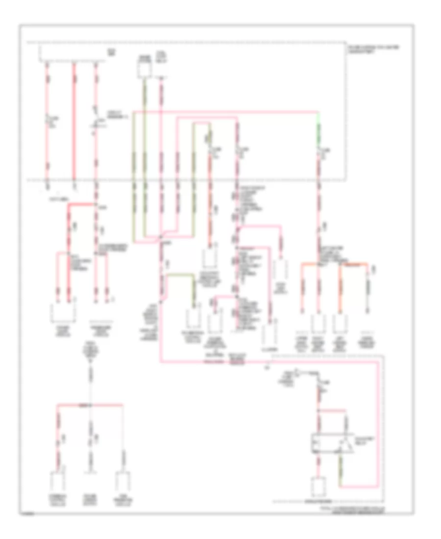
Power Distribution Wiring Diagram (2 of 4) for Dodge Challenger SXT Plus 2013
List of elements for Power Distribution Wiring Diagram (2 of 4) for Dodge Challenger SXT Plus 2013:
- (in driver's door harness) s420
- (in passenger's door harness) s520
- (left center of dash) g10a
- (near battery) power distribution center
- (not used)
- 15b
- 17b
- 18b
- 18c
- 19b
- 23b
- 23c
- 35a
- 35b
- 46a
- 47a
- 47c
- Accessory delay relay
- Active damping control unit (if equipped)
- Batt (+) fd
- Brake lamp relay
- Btsi sol ulk
- Bus bar
- C102
- C104
- C200
- C203
- C300
- C301
- Can c (+)
- Can c (-)
- Center high mounted stop lamp
- Cigar lighter
- Circuit board
- Cluster
- Clutch interlock switch (m/t)
- Computer data lines system
- Data link connector
- Driver window/ door express down switch
- Fuel pump relay
- Fuse 15a
- Fuse 20a
- Fuse 5a
- G10a (left center of dash)
- Gnd
- Ign run st
- Intrlk strt fd
- Intrlk strt fd2
- Left front led handle lamp
- Passenger window/door express down switch
- Passive entry module
- Pnk
- Power mirror switch
- Powertrain control module (m/t)
- Rear heated seats relay
- Rear window defogger relay
- Red
- Red/tan
- Right front led handle lamp
- S215 (right side of dash, in instrument panel harness)
- S300
- S302
- S323
- Shift lever assembly (a/t)
- Stop lamp switch
- Stp lmp fd
- Totally integrated power module (right side of engine compt)
- Trans rng park
- Wireless ignition node
Power Distribution Wiring Diagram (3 of 4) for Dodge Challenger SXT Plus 2013
List of elements for Power Distribution Wiring Diagram (3 of 4) for Dodge Challenger SXT Plus 2013:
- (center of dash, in instrument panel harness) s210
- (near battery) power distribution center
- (right side of dash, in instrument panel harness) s200
- 14a
- 14b
- 21b
- 21c
- 28a
- 28b
- 31a
- 31b
- 36a
- 36b
- 38a
- 38b
- 42a
- 42b
- 44a
- 44b
- 47d
- A/c heater control
- A/c heater module
- Bus bar
- C104
- C200
- C202
- C203
- C204
- C311
- Cargo lamp
- Circuit board
- Cluster
- Diode
- Electronic overhead module
- Front power blower motor module
- Fuse 10a
- Fuse 20a
- Fuse 30a
- Hands free module
- In car temperature sensor
- Iod-pdc
- Occupant restraint controller module
- Park assist module
- R/t
- Radio
- Radio amplifier (if equipped)
- Rear heated seats relay
- Red
- Run relay
- S202
- S203 (right end of dash, in instrument panel harness)
- S313
- S321
- S322
- S374
- S388
- Sunroof module/motor
- Totally integrated power module (right side of engine compt)
- Transmission relay
Power Distribution Wiring Diagram (4 of 4) for Dodge Challenger SXT Plus 2013
List of elements for Power Distribution Wiring Diagram (4 of 4) for Dodge Challenger SXT Plus 2013:
- (if equipped) s336
- (in passenger's door harness) s510
- (left center of dash, in instrument panel harness) s217
- (not used)
- (right side of luggage compt, in body harness)
- 11b
- 12b
- 20b
- 25a
- 27a
- 27b
- 29a
- 29b
- 32a
- 40a
- 40b
- 46c
- Anti-lock brakes module
- Bus bar
- C102
- C104
- C200
- C203
- C205
- C300
- C301
- Circuit board
- Circuit breaker 12
- Cluster
- Dash, in instrument panel harness)
- Driver door module
- From a fuse 1 (diagram 1 of 4)
- From fuse 30 (diagram 1 of 4)
- Fuel pump relay
- Fuse 10a
- Fuse 20a
- Fuse 5a
- Inside rearview mirror
- Left heated seat switch
- Nca
- Occupant restraint controller module
- Passenger door module
- Power distribution center (near battery)
- Power mirror switch
- Power steering pump motor (if equipped)
- Powertrain control module
- Red
- Right heated seat switch
- Run/start relay
- S128 (w/ power steering) (under left side of rear shelf, in body harness)
- S167 (right rear of engine compt, in headlamp & dash harness)
- S305
- S309
- S410 (in driver's door harness)
- Steering control module
- Stop lamp switch
- Tire pressure module
- Totally integrated power module (right side of engine compt)
- Upper bank switch (6.4l)
- Zener diode

 Čeština
 Dansk
Dansk Deutsch
 Ελληνικά
 English
 Español
 Suomi
Suomi Français
 Français
 עברית
עברית Hrvatski
 Magyar
 Italiano
 日本語
日本語 한국어
한국어 Nederlands
 Polski
 Português
 Português
 Română
 Русский
 Slovenčina
 Slovenščina
 Svenska
 Türkçe
 中文 (中国)