POWER DISTRIBUTION
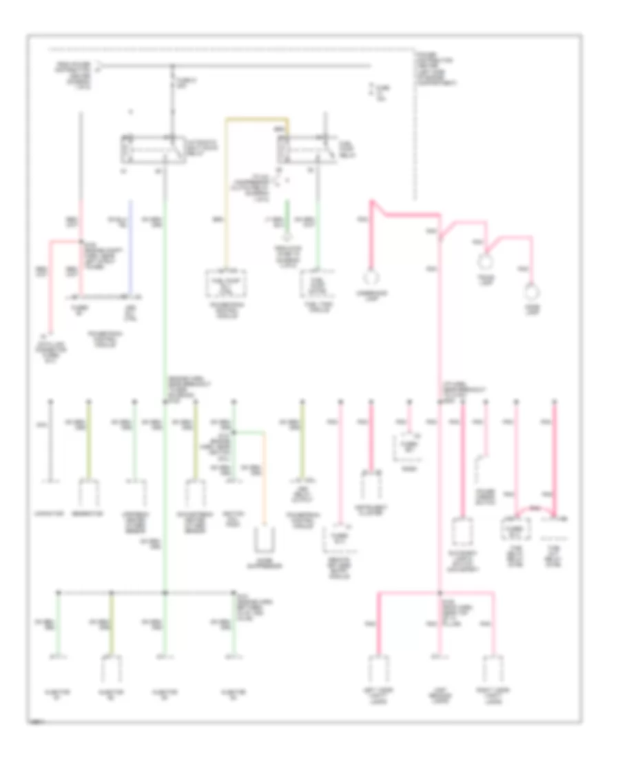
Power Distribution Wiring Diagram (1 of 5) for Dodge Neon 1997
 https://portal-diagnostov.com/license.html
Automotive Electricians Portal FZCO
Automotive Electricians Portal FZCO
https://portal-diagnostov.com/license.html
https://portal-diagnostov.com/license.html
Automotive Electricians Portal FZCO
Automotive Electricians Portal FZCO
List of elements for Power Distribution Wiring Diagram (1 of 5) for Dodge Neon 1997:
- (left side of engine compartment) power distribution center
- A/c clutch relay control
- A/c compressor clutch
- A/c compressor clutch relay
- A/t
- Abs relay box
- Battery
- Cavity
- Cavity 10
- Clockspring
- Clutch pedal position switch
- Diode
- Engine starter motor
- Engine starter motor relay
- From fuel pump relay (diagram 2 of 5)
- Fuse 10a
- Fuse 15a
- Fuse 30a
- Fuse 40a
- G100 (left side of radiator closure panel)
- Horn
- Horn relay
- Horn relay control
- Horn switches
- M/t
- Nca
- Park/ neutral position switch
- Park/ neutral switch
- Powertrain control module
- Rear window defogger switch
- Red
- Remote keyless entry module
- S106 (engine compt. harn, near breakout to pcm)
- S107
- S213 (i/p harn, near breakout to fuse block)
- Solid state fan relay
- Stop lamp/ vehicle speed control switch
- To fuse block (fuses 1, 3 & 4) (diagram 4 of 5)
- To headlamp switch (diagram 5 of 5)
- To ignition switch (diagram 3 of 5)
- To power distribution center (diagram 2 of 5)
- Turn signal/ hazard switch
- W/remote keyless entry
Power Distribution Wiring Diagram (2 of 5) for Dodge Neon 1997
List of elements for Power Distribution Wiring Diagram (2 of 5) for Dodge Neon 1997:
- (engine harn, near breakout to egr solenoid) s122
- (i/p harn, near breakout to hvac) s203
- Asd relay output
- Asd rly ctrl
- Automatic shut down relay
- Capacitor
- Data link connector fused b (+)
- Dome lamp
- Downstream heated oxygen sensor
- From power distribution center (diagram 1 of 5)
- From s109 (fuse 10) (diagram 3 of 5)
- Fuel pump motor
- Fuel pump relay
- Fuel pump rly ctrl
- Fuel tank module
- Fuse 10a
- Fuse 21 20a
- Fused (b+)
- Fused b (+)
- Fused b+
- Generator
- Glove box lamp & switch (max-sport)
- Ignition coil pack
- Injector #1
- Injector #2
- Injector #3
- Injector #4
- Instrument cluster
- Left visor/ vanity lamps
- Map/ reading lamps
- Nca
- Noise suppressor
- Pnk
- Power distribution center (left side of engine compartment)
- Power mirror switch
- Powertrain control module
- Radio
- Remote keyless entry module
- Right visor/ vanity lamps
- S105 (engine compt. harn, near left strut tower)
- S105 (roof harn, near top of "a" pillar) pnk
- S121 (engine harn, between inj #1 and inj #2)
- S127 (engine harn, near ignition coil)
- Time delay relay (in fb)
- Time out relay (in fb)
- To a/c compressor clutch relay (diagram 1 of 5)
- Trunk lamp
- Underhood lamp
- Upstream heated oxygen sensor
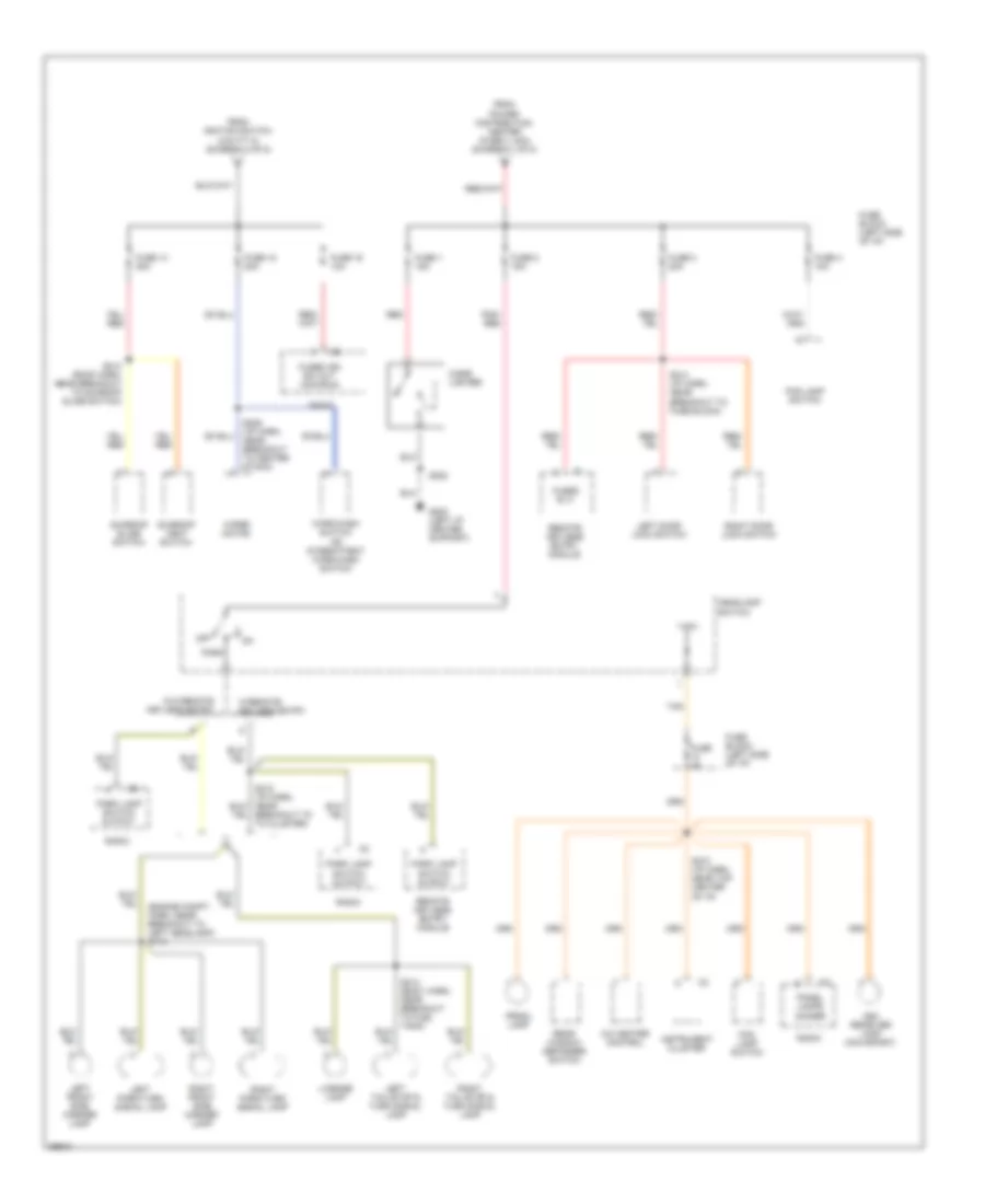
Power Distribution Wiring Diagram (3 of 5) for Dodge Neon 1997
List of elements for Power Distribution Wiring Diagram (3 of 5) for Dodge Neon 1997:
- (engine compt. harn, near breakout to left headlamp) s109
- (engne compt. harn, near breakout to pcm) s217
- 30a
- A/c cycling switch
- A/c heater blower motor
- A/t
- A/t only
- Abs relay box
- Acc
- Airbag control module
- Back-up lamp switch
- Controller anti-lock brake
- Daytime running lamp module
- Duty cycle evap/purge solenoid
- Egr transducer solenoid
- From engine starter motor relay (a/t) or clutch pedal position switch (m/t) (diagram 1 of 5)
- From power distribution center (fuse 11, 30a) (diagram 1 of 5)
- From power distribution center (fuse 2, 40a) (diagram 1 of 5)
- Fuse 10a
- Fuse 25a
- Fuse 5a
- Fuse block (left side of i/p)
- Fused ign sw (out) (run)
- Fused ign sw (run/start)
- Fused ign sw out (run/start)
- Ignition switch
- Instrument cluster
- M/t
- Master power window switch
- Off
- Park/ neutral position switch
- Power windows circuit breaker
- Powertrain control module
- Rear window defogger switch
- Red
- Remote keyless entry module
- Right door power window switch
- Run
- Run off
- S211 (i/p harn, near breakout to cluster)
- S217 (i/p harn, in breakout to fuse block)
- S219 (i/p harn, near breakout to cluster)
- Start
- Tan
- To fuse block (fuses 14, 15 & 16) (diagram 4 of 5)
- To power distribution center (diagram 2 of 5)
- Torque converter clutch solenoid
- Turn signal/ hazard switch
- Vapor canister leak detector
- W/ power windows
- W/o power windows
- W/o remote keyless entry
- W/remote keyless entry
Power Distribution Wiring Diagram (4 of 5) for Dodge Neon 1997
List of elements for Power Distribution Wiring Diagram (4 of 5) for Dodge Neon 1997:
- (engine compt. harn, near breakout to left headlamp) s113
- A/c heater control
- Ash receiver lamp (max-sport)
- Breakout to to cluster)
- Cigar lighter
- Fog lamp switch
- From ignition switch (cavity 8) (diagram 3 of 5)
- From power distribution center (fuse 3, 40a) (diagram 1 of 5)
- Fuse 1 15a
- Fuse 14 20a
- Fuse 15 20a
- Fuse 16 10a
- Fuse 2 15a
- Fuse 3 20a
- Fuse 4 10a
- Fuse 4a
- Fuse block (left side of i/p)
- Fused b (+)
- Fused ign sw out (acc/run)
- G202 (left i/p center support)
- Headlamp switch
- Instrument cluster
- Left door lock switch
- Left front side marker lamp
- Left park/turn signal lamp
- Left tail/stop & turn signal lamp
- License lamp
- Off
- Panel lamps dimmer
- Park
- Park lamp switch output
- Pnk/ red
- Prndl lamp
- Radio
- Rear window defogger switch
- Red
- Remote keyless entry module
- Right door lock switch
- Right front side marker lamp
- Right park/turn signal lamp
- Right tail/stop & turn signal lamp
- S202
- S206 (i/p harn, near breakout to center stack)
- S210 (i/p harn, near top center of i/p)
- S214 (body harn, near breakout to fuel tank)
- S214 (i/p harn, near breakout to fuse block)
- S313 (roof harn, near breakout to sunroof slide switch)
- Sunroof slide switch
- Sunroof vent switch
- Tan
- W/o remote keyless entry
- W/remote keyless entry
- Wipe/wash switch or intermittent wipe/wash switch
- Wiper motor
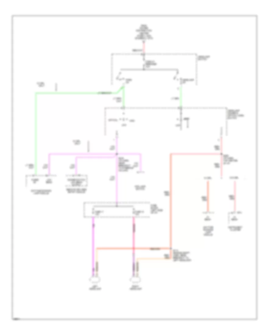
Power Distribution Wiring Diagram (5 of 5) for Dodge Neon 1997
List of elements for Power Distribution Wiring Diagram (5 of 5) for Dodge Neon 1997:
- Circuit breaker 24a
- Daytime running lamp module
- Dimmer switch low beam output
- Fog lamp switch
- From power distribution center (fuse 3, 40a) (diagram 1 of 5)
- Fuse 17 10a
- Fuse 18 10a
- Fuse block (left side of i/p)
- Fused b+
- Headlamp dimmer & optical horn switch
- Headlamp on
- Headlamp switch
- Hi beam
- High
- Instrument cluster
- Left headlamp
- Low
- Low beam
- Optical
- Park on
- Remote keyless entry module
- Right headlamp
- S114 (engine compt. harn, near breakout to left headlamp)
- S209 (i/p harn, top center of i/p)
- S216 (i/p harn, near breakout to steering column)
- W/ drl
- W/ drl only
- W/o drl

 Čeština
 Dansk
Dansk Deutsch
 Ελληνικά
 English
 Español
 Suomi
Suomi Français
 Français
 עברית
עברית Hrvatski
 Magyar
 Italiano
 日本語
日本語 한국어
한국어 Nederlands
 Polski
 Português
 Português
 Română
 Русский
 Slovenčina
 Slovenščina
 Svenska
 Türkçe
 中文 (中国)