POWER DISTRIBUTION
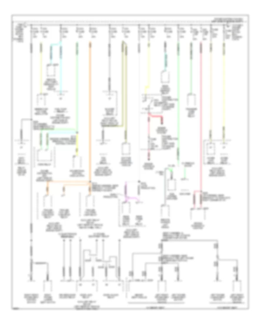
Power Distribution Wiring Diagram (1 of 5) for Ford Explorer 1997
 https://portal-diagnostov.com/license.html
Automotive Electricians Portal FZCO
Automotive Electricians Portal FZCO
https://portal-diagnostov.com/license.html
https://portal-diagnostov.com/license.html
Automotive Electricians Portal FZCO
Automotive Electricians Portal FZCO
List of elements for Power Distribution Wiring Diagram (1 of 5) for Ford Explorer 1997:
- (early prod.)
- (eatc)
- (engine harness, near breakout for for fuel injector #3) s118
- (engine harness, near breakout to 4wabs control module) s115
- (engine harness, near breakout to conn c123, behind battery) s134
- (engine harness, near breakout to conn c146, left rear of engine compt) s116
- (i/p harness, in breakout to headlamp switch) s162
- (i/p harness, in breakout to ignition switch) s204
- (i/p harness, near breakout to i/p)
- (i/p harness, near breakout to i/p) s213
- (interior fuse panel)
- (late prod.)
- (late production) (early production)
- (not used)
- 4.0l & 5.0l
- 4wabs control module
- 4wabs main relay
- 5.0l
- A/t w/o dtr
- A1 (not used)
- Acc
- Air bag diagnostic monitor
- Air bag diagnostic monitor (eatc only)
- Air bag diagnostic monitor (w/o eatc)
- Automatic ride control module
- Auxiliary relay box #1 (left side of engine compt)
- Auxiliary relay box #2 (right front of engine compt)
- Backup lamp switch
- Battery
- Blend door actuator
- Blower motor relay
- Brake fluid level warning switch
- Brake pressure switch
- C122
- C2001
- C2008
- C231
- C232
- C233
- C283
- C286
- C287
- C288
- C297
- C332
- Compass/ outside air temperature module
- Day/night mirror/ autolamp sensor
- Daytime running lamps (drl) module
- Digital transmission range sensor
- Dimmer relay
- Electronic automatic temperature control (eatc) module module (eatc)
- Fuse 10a
- Fuse 15a
- Fuse 25a
- Fuse 7.5a
- Fuse maxi 60a
- Generator/ voltage regulator
- Generic electronic module (gem)
- Heater-a/c control assembly
- Ignition coil
- Ignition switch
- Instrument cluster
- Interior fuse panel (left side of i/p)
- Lamp out warning module
- Lock
- M/t
- Message center
- Off
- Pcm power diode
- Pcm power relay
- Pnk
- Power distribution box (left side of engine compt)
- Radio noise capacitor
- Rear blower motor relay
- Rear integrated control panel (ricp)
- Rear window defrost relay
- Red
- Relay module (center of i/p)
- Run
- S141
- S211
- S240 (body harness, in breakout to conn c323, left rear door jamb)
- S241
- Shift lock actuator
- Speed control servo/ amplifier assembly
- Start
- Starter motor
- Starter relay
- Steering sensor
- To fuse 20 (diagram 4 of 5)
- To fuse 24 (diagram 4 of 5)
- To fuse 5 (power distribution box) diagram 2 of 5)
- Transmission control switch (tcs)
- Transmission range (tr) sensor
- Turn/ hazard flasher
- W/ eatc
- W/o eatc
Power Distribution Wiring Diagram (2 of 5) for Ford Explorer 1997
List of elements for Power Distribution Wiring Diagram (2 of 5) for Ford Explorer 1997:
- (body harness, in breakout for liftgate washer pump motor) s303
- (early production)
- 15a
- 20a
- 30a
- 4wabs main relay
- 4wabs pump relay
- 50a
- Accy delay relay
- Air bag diagnostic monitor
- Amplifier
- Auxiliary relay box #1 (left side of engine compt)
- Auxiliary relay box #2 (right front of engine compt)
- Auxiliary relay box #4 (left rear of vehicle, above wheel well)
- Blower motor relay
- C121
- C232
- C335
- C338
- C350
- Daytime running lamps (drl) module
- Door
- Door lock relay
- Door unlock relay
- Driver's door unlock relay
- Engine controls system
- Fog lamp relay
- From a fuse 1 (power distri- bution box) (diagram 1 of 5)
- Fuel pump relay
- Fuse
- Fuse maxi 30a
- Fuse mini 15a or 20a
- Generator/ voltage regulator
- Horn relay
- Left front power seat control switch
- Left power lumbar seat switch
- Maxi
- Memory seat module
- Mini
- Mini fuse 4 or 20a
- Nca
- Pcm power relay
- Power distribution box (left side of engine compt)
- Powertrain control module (pcm)
- Rear window defrost relay
- Rear wiper down relay
- Rear wiper up relay
- Red
- Relay module (center of i/p)
- Remote anti-theft personality (rap) module
- Remote chassis unit (radio)
- Right front power seat control switch
- Right power lumbar seat switch
- S113 (engine harness, near breakout to power distribution box)
- S114 (engine harness, near breakout to power distribution box)
- S219 (late production)
- S236 (i/p harness, near breakout to headlamp switch)
- S239 (i/p harness, near breakout to conn c213, right corner of i/p)
- S317
- Sub woofer amplifier
- To fuse 8 (power distri- bution box) (diagram 3 of 5)
- Trailer tow left turn/stop relay
- Trailer tow park lamp relay
- Trailer tow right turn/stop relay
- Transfer case shift relay
- W/ electronics group only
- W/ jbl
- W/ memory seat
- W/ power equipment group
- W/ premium sound
- W/o memory seat
Power Distribution Wiring Diagram (3 of 5) for Ford Explorer 1997
List of elements for Power Distribution Wiring Diagram (3 of 5) for Ford Explorer 1997:
- (body harness, in breakout to conn c267, left "a" pillar) s334
- (diagram 2 of 5)
- (i/p harness, near breakout for i/p) s246
- (i/p harness, near breakout to conn c291, left side of i/p) s237
- (i/p harness, near breakout to g204) s322
- (i/p harness, near breakout to relay module) s238
- 15a
- 20a
- 30a
- 50a
- Accy delay relay
- Automatic ride control (arc) off/on switch
- Automatic ride control relay
- Auxiliary relay box #1 (left side of engine compt)
- Auxiliary relay box #3 (left rear of engine compt)
- Auxiliary relay box #4 (left rear of vehicle, above wheel well)
- Battery saver relay
- C280
- Compass/ outside air temperature module
- Defogger system
- Dimmer module
- Dimmer relay
- Dimmer switch
- Exterior lights system
- Flash- to-pass switch
- From maxi d fuse 5 (power distribution box)
- Fuse 10a
- Fuse 15a
- Fuse 1oa
- Fuse 7.5a
- Generic electronic module (gem)
- Glove box lamp & switch
- Head
- Head- lamp switch
- Headlamp relay (w/ autolamps)
- Headlamp switch
- Headlights system
- Interior fuse panel (left side of i/p)
- Interior lamp relay
- Left vanity mirror lamp
- Low
- Map lamp
- Maxi fuse
- Mini fuse
- Multi- function switch
- Nca
- Off
- Park
- Park lamp relay
- Pass
- Pnk
- Power distribution box (left side of engine compt)
- Rear map lamp
- Rear wiper down relay
- Rear wiper up relay
- Relay module (center of i/p)
- Right vanity mirror lamp
- S266 (i/p harness, near breakout to headlamp switch)
- To maxi fuse 3 (power distribution box) (diagram 4 of 5)
- Transfer case shift relay
- Underhood lamp
- W/o overhead console
Power Distribution Wiring Diagram (4 of 5) for Ford Explorer 1997
List of elements for Power Distribution Wiring Diagram (4 of 5) for Ford Explorer 1997:
- (adaptive suspension)
- (body harness, near breakout power antenna module) s355
- (diagram 1 of 5)
- (engine harness, near breakout power distribution box) s163
- (i/p harness, near breakout for i/p) s245
- (other)
- A/t
- Anti-theft relay
- Auxiliary power
- Auxiliary relay box #2 (right front of engine compt)
- Brake on/off (boo) switch
- C2009
- C228
- C283
- C291
- C297
- C335
- C336
- C350
- C364
- C435
- Clutch pedal position (cpp) switch
- Clutch pedal position (cpp) switch jumper
- Data link connector
- Day/night mirror/autolamp sensor
- Electronic automatic temperature control (eatc) module
- From ignition switch
- From maxi e fuse 12 (power distribution box) (diagram 3 of 5)
- Front washer pump relay
- Fuse 10a
- Fuse 15a
- Fuse 2 (interior fuse panel) (diagram 5 of 5)
- Fuse 30a
- Fuse 7.5a
- G104 (left rear corner of engine compt. at fender apron)
- Generic electronic module (gem)
- Interior fuse panel (left side of i/p)
- Liftgate wiper/washer switch
- M/t
- Maxi fuse 60a
- Memory seat module
- Message center
- Mini fuse 30a
- Mobile telephone transceiver
- Pnk
- Power antenna module
- Power distribution box (left side of engine compt)
- Power mirror switch
- Radio or front control unit
- Red
- Relay module (center of i/p)
- Remote anti-theft/ personality (rap) module
- Remote chassis unit (radio)
- S165 (engine harness, near breakout for conn c115, left rear of engine compt)
- S200
- S209
- S212 (i/p harness, near breakout to dlc)
- S408
- Starter relay
- To fuse (interior fuse panel) (diagram 5 of 5)
- To ignition switch
- Transmission range (tr) sensor
- W/ memory seat
- W/o center console only
- W/o memory seat
- Wiper hi-lo relay
- Wiper motor
- Wiper run relay
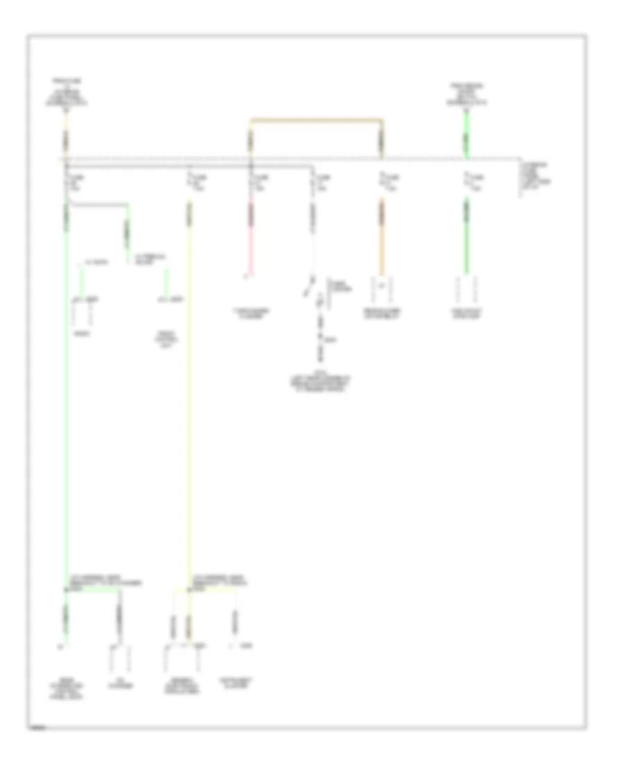
Power Distribution Wiring Diagram (5 of 5) for Ford Explorer 1997
List of elements for Power Distribution Wiring Diagram (5 of 5) for Ford Explorer 1997:
- (i/p harness, near breakout to cd changer) s243
- (i/p harness, near breakout to radio) s242
- C228
- C283
- C288
- Cd changer
- Cigar lighter
- From brake on/off switch (diagram 4 of 5)
- From fuse (interior fuse panel) (diagram 4 of 5)
- Front control unit
- Fuse 10a
- Fuse 15a
- Fuse 7.5a
- G104 (left rear corner of engine compartment, at fender apron)
- Generic electronic module (gem)
- High mount stoplamp
- Instrument cluster
- Interior fuse panel (left side of i/p)
- Radio
- Rear blower motor relay
- Rear integrated control panel (ricp)
- S200
- Turn/hazard flasher
- W/ am/fm
- W/ premium sound

 Čeština
 Dansk
Dansk Deutsch
 Ελληνικά
 English
 Español
 Suomi
Suomi Français
 Français
 עברית
עברית Hrvatski
 Magyar
 Italiano
 日本語
日本語 한국어
한국어 Nederlands
 Polski
 Português
 Português
 Română
 Русский
 Slovenčina
 Slovenščina
 Svenska
 Türkçe
 中文 (中国)