POWER DISTRIBUTION
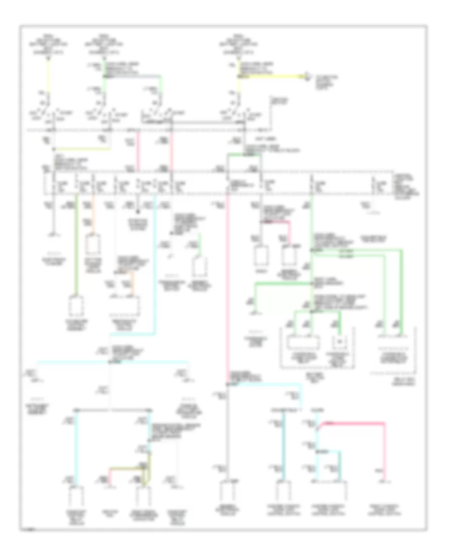
Power Distribution Wiring Diagram (1 of 3) for Ford Mustang 2000
 https://portal-diagnostov.com/license.html
Automotive Electricians Portal FZCO
Automotive Electricians Portal FZCO
https://portal-diagnostov.com/license.html
https://portal-diagnostov.com/license.html
Automotive Electricians Portal FZCO
Automotive Electricians Portal FZCO
List of elements for Power Distribution Wiring Diagram (1 of 3) for Ford Mustang 2000:
- (1999)
- (1999-00)
- (2000)
- (body harn, near breakout to conv lower relay) s409
- (body harn, near breakout to generic electronic module) s269
- (dash panel to headlamp junction harn, in breakout to battery junction block)
- (eng cntrl sens harn, right side of engine compt)
- (main harn, below rear of center console) s273
- (main harn, left side of dash) s236
- (main harn, near breakout to rear window defrost control switch) s233
- (main harn, near breakout to rear window defrost control switch) s242
- (main harn, near breakout to restraints control module) s270
- (main harness, left rear engine compt) s260
- 3.8l
- 3.8l (1999)
- 30a
- 4.6l
- 4.6l 3.8l
- A/c pressure fuse 20a
- Abs fuse 20a
- Abs fuse 50a
- Air injection reaction relay
- Alt fuse 20a
- Anti-lock brake control module
- Audio fuse 10a
- Auxiliary power socket
- Battery
- Battery junction box (in left side of engine compt, forward of strut tower)
- C280
- C281
- C290
- C291
- Cd player
- Central junction box (behind dash, left of steering column)
- Cigar lighter
- Constant control relay module
- Conv top circuit breaker 25a
- Data link connector
- Daytime running lights module
- Driver's seat control switch
- Electronic flasher
- Exterior rear view mirror switch
- Fan circuit breaker 30a
- Fan fuse 50a
- Fog lamps relay
- Fog, drl fuse 20a
- Fuel pump fuse 20a
- Fuse 10a
- Fuse 15a
- Fuse 20a
- Fuse 25a
- G300 (below rear of center console)
- Generator
- Generic electronic module
- Hd lps fuse 30a
- Horn fuse 20a
- Horn relay
- Htd bl fuse 30a
- Ign sw fuse 40a
- Int i/p fuse 40a
- Lower relay
- Luggage compt lid relay
- Luggage compt lid release switch
- Main light switch
- Master window/ door lock control switch
- Multi- function switch
- Nca
- Park lamp relay
- Park lamps fuse 30a
- Pcm power fuse 30a
- Power point fuse 20a
- Power seat fuse 25a
- Power windows fuse 40a
- Radio
- Raise relay
- Rear window defrost control switch
- Red
- Relay box (near dash)
- Right window/ door lock control switch
- S102
- S108
- S109 (dash panel to headlamp junction harn, lower left side of eng compt)
- S111
- S303
- S303 (console panel harn, near breakout to auxiliary power socket)
- S504 (left door/ window regulator harn, near breakout to left door speaker)
- Starter motor/ solenoid
- Starter relay
- Therm fuse 30a
- To fuse 27 (diagram 3 of 3)
- To ignition switch (diagram 2 of 3)
- To splice s215 (diagram 2 of 3)
- To splice s217 (diagram 2 of 3)
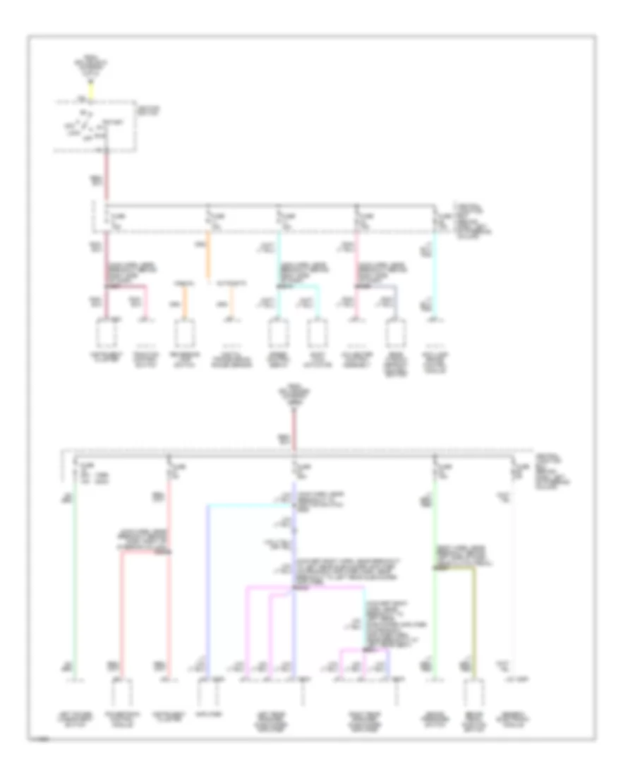
Power Distribution Wiring Diagram (2 of 3) for Ford Mustang 2000
List of elements for Power Distribution Wiring Diagram (2 of 3) for Ford Mustang 2000:
- (body harn, near grommet) s312
- (dash panel to headlamp junction harn, near breakout at lower left side of engine compt) s113
- (engine control sensor harn, near breakout to right front brake sensor) s174
- (main harn, near breakout to generic electronic module) s262
- (main harn, near breakout to ignition switch) s215
- (main harn, near breakout to ignition switch) s217
- (main harn, near breakout to relay block) s264
- (main harn, near breakout to relay block) s267
- (main harn, near breakout to shift lock actuator) s243
- (main harn, near breakout to shift lock actuator) s265
- (main harn, near breakout to shift lock actuator) s266
- (main harn, near breakout to window defrost control switch) s225
- (not used)
- 3.8l
- 4.6l
- A/c-heater control assembly
- Acc
- Battery junction box
- C290
- C352
- Central junction box (behind dash, left of steering column)
- Circuit breaker 43 20a
- Constant control relay module
- Convertible
- Convertible top switch
- Coupe
- Daytime running lamps module
- Electronic flasher
- From ign sw fuse (battery junction box) (diagram 1 of 3)
- Fuse 15a
- Fuse 20a
- Fuse 30a
- Generic electronic module
- Ignition coil
- Ignition switch
- Instrument cluster assembly
- Lock
- Master window/ door lock control switch
- Off
- Passive anti-theft transceiver module
- Pnk
- Radio
- Relay box (near dash)
- Restraints control module
- Right radio interference capacitor
- Right window/ door lock control switch
- Run
- S211 (main harn, near breakout to ignition switch)
- S505
- Sta
- Start
- Starting/ charging system
- To ignition switch (diagram 3 of 3)
- Transmission control switch
- Windshield washer pump motor relay
- Windshield wiper high/low relay
- Windshield wiper motor
- Windshield wiper on/off relay
Power Distribution Wiring Diagram (3 of 3) for Ford Mustang 2000
List of elements for Power Distribution Wiring Diagram (3 of 3) for Ford Mustang 2000:
- (1999) (2000)
- (body harn, near breakout behind left side of dash, near clutch pedal) s207
- (convert-body harn, near breakout to left rear subwoofer amplifier, coupe-radio amplifier harn, near breakout to left rear subwoofer amplifier) s432
- (main harn, near breakout behind dash, right of steering column) s259
- (main harn, near breakout behind right side of dash) s245
- (main harn, near breakout behind right side of dash) s256
- (main harn, near breakout behind right side of dash) s257
- (main harn, near breakout to ignition switch) s258
- A/c heater control assembly
- Acc
- Amplifier
- Anti-lock brake control module
- Automatic
- Brake pedal position switch
- Brake pressure switch
- C251
- C282
- C291
- C408
- C409
- Central junction box (behind dash, left of steering column)
- Digital transmission range sensor
- From splice s215 (diagram 2 of 3)
- From splice s260 (diagram 1 of 3)
- Fuse 15a
- Fuse 20a 15a
- Fuse 25a
- Fuse 5a
- Generic electronic module
- Ignition switch
- Instrument cluster
- Left power lumbar seat switch
- Left rear speaker subwoofer amplifier
- Lock
- Manual
- Off
- Powertrain control module
- Rear window defrost control switch
- Reversing lamp switch
- Right rear speaker subwoofer amplifier
- Run
- Shift lock actuator
- Speed control servo
- Start
- Traction control switch

 Čeština
 Dansk
Dansk Deutsch
 Ελληνικά
 English
 Español
 Suomi
Suomi Français
 Français
 עברית
עברית Hrvatski
 Magyar
 Italiano
 日本語
日本語 한국어
한국어 Nederlands
 Polski
 Português
 Português
 Română
 Русский
 Slovenčina
 Slovenščina
 Svenska
 Türkçe
 中文 (中国)