POWER DISTRIBUTION
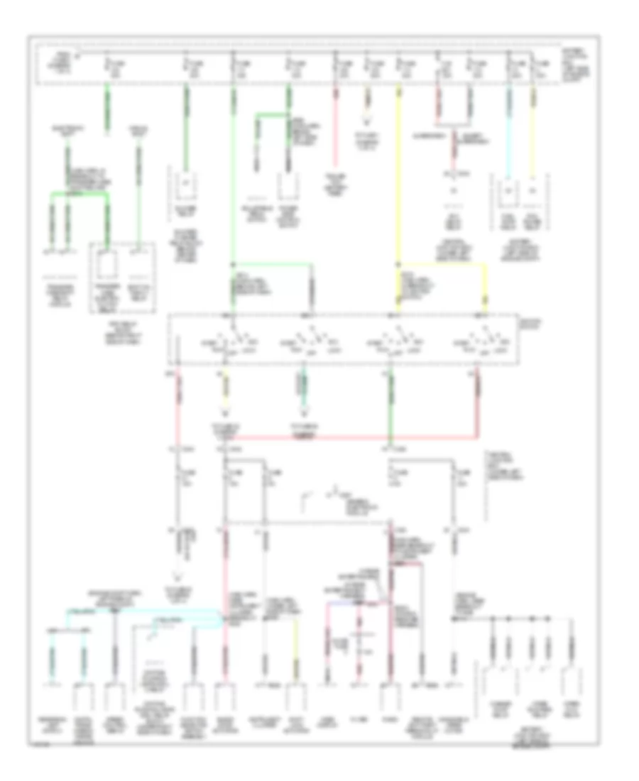
Power Distribution Wiring Diagram (1 of 4) for Ford Pickup F150 2001
 https://portal-diagnostov.com/license.html
Automotive Electricians Portal FZCO
Automotive Electricians Portal FZCO
https://portal-diagnostov.com/license.html
https://portal-diagnostov.com/license.html
Automotive Electricians Portal FZCO
Automotive Electricians Portal FZCO
List of elements for Power Distribution Wiring Diagram (1 of 4) for Ford Pickup F150 2001:
- (battery harness, near red battery) s1001
- (body harn, near breakout to park brake switch) s216
- (engine harn, near 4wabs module) s171
- (engine harness, left side of engine compt) s109
- (main harn, behind left side of dash) s212
- (main harn, near breakout to passenger's air bag) s241
- 4 wheel anti-lock brake system (4wabs) module
- All lock relay
- All unlock relay
- Auxiliary power socket
- Battery
- Battery junction box (left side of engine compt)
- Bi-fuel power relay
- Bi-fuel relay module (right rear of engine compt)
- C257
- Central security module
- Charge air cooler pump relay
- Cold start heater relay
- Compuvalve module
- Daytime running lamps resistor
- Driver heated seat module
- Driver's unlock relay
- Except supercrew
- Fog lamp relay
- From a fuse 8 (diagram 1 of 4)
- Fuse 10a
- Fuse 15a
- Fuse 20a
- Fuse 30a
- Fuse 3a
- Fuse 50a
- G203 (lower right kick panel)
- Generator
- Headlamp relay
- Horn relay
- Left power door lock switch
- Lock relay block (behind right side of dash)
- Main light switch
- Multi- function switch
- Park lamp relay
- Passenger heated seat module
- Rear power point
- Red
- Right power door lock switch
- Rpo relay block (behind right side of dash)
- S1002 (battery harness, near battery)
- S108 (engine compt harn, in breakout to bjb)
- S205
- S304
- S320 (safety belt harn, near pass seat)
- Starter motor
- Starter motor relay
- Supercrew
- To fuse (diagram 1 of 4)
- To fuse (diagram 2 of 4)
- Trailer tow back-up lamp relay
- Trailer tow battery charge relay
- Trailer tow running lamp relay
- W/ rap
- W/ security
- W/auto lamps
- W/o rap or security
- Wot battery
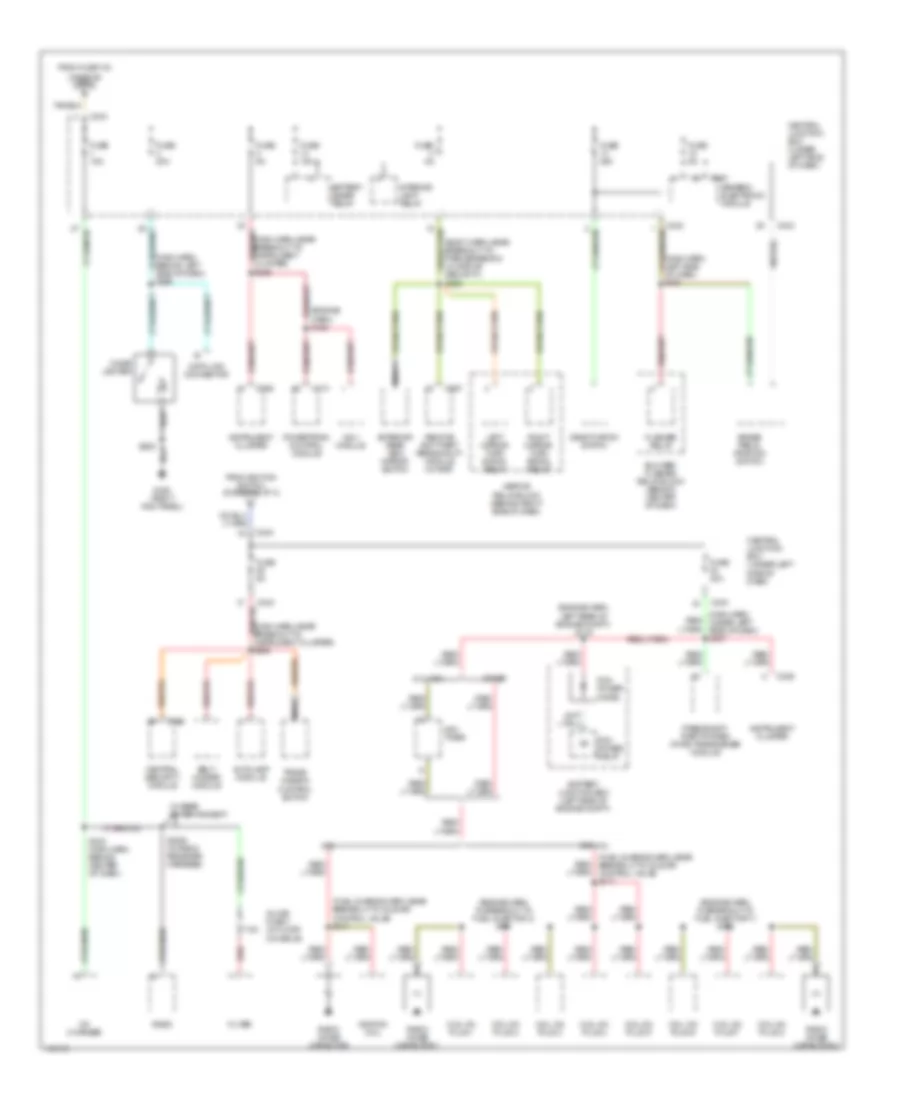
Power Distribution Wiring Diagram (2 of 4) for Ford Pickup F150 2001
List of elements for Power Distribution Wiring Diagram (2 of 4) for Ford Pickup F150 2001:
- (diagram 3 of 4)
- (engine compt harn, left rear of engine compt) s112
- (engine harn, near breakout to bjb) s113
- (in rear entertainment harness) s355 pnk
- (main harn, in breakout to transfer case shift relays) s213
- (main harn, near instrument cluster breakout) s222
- (main harn, near breakout to instrument cluster) s223
- (main harn, under left side of dash) s265
- 7.5a
- A/t
- Acc
- Acc delay relay
- Adjustable pedal switch
- Battery junction box (left side of engine compt)
- Blend door actuator
- Blower relay
- Blower/ flasher relay block (behind center of dash)
- C.b. 30a
- C236
- C242
- C243
- C256
- C267
- Central junction box (under left side of dash)
- Daytime running lamps (drl) 2 relay
- Daytime running lamps (drl) relay block (under right side of dash)
- Digital trans- mission range sensor
- Electronic shift
- Except supercrew
- Filter
- From b fuse 3 (diagram 1 of 4)
- Fuel pump relay
- Function selector switch assembly
- Fuse 15a
- Fuse 20a
- Fuse 30a
- Fuse 40a
- Fuse 50a
- Fuse 5a
- Generic electronic module
- Ignition switch
- Inline fuse
- Instrument cluster
- Lock
- M/t
- Manual shift
- Nca
- Off
- Pcm power relay
- Pnk
- Power seat control switch
- Radio
- Red
- Remote anti-theft personality module
- Reversing lamp switch
- Rpo relay block (behind right side of dash)
- Run
- S2003 (in radio receiver harness)
- S214 (main harn, behind left side of dash)
- S215 (main harn, in breakout to ignition switch)
- Shift lock actuator
- Shift on the fly relay
- Speed control servo
- Start
- Supercrew
- To fuse 1
- To fuse 20 (diagram 4 of 4)
- To fuse 22 (diagram 4 of 4)
- To fuse 29
- Trailer tow (battery feed)
- Transfer case electric clutch relay
- Transfer case shift relay module
- Video display
- W/ rear entertainment
- Washer pump relay
- Windshield wiper motor
- Wiper hi/lo relay
- Wiper run/park relay
Power Distribution Wiring Diagram (3 of 4) for Ford Pickup F150 2001
List of elements for Power Distribution Wiring Diagram (3 of 4) for Ford Pickup F150 2001:
- (body harn, near breakout to park brake sw) (w/ rap or security) s220
- (diagram 2 of 4) c
- (engine
- (engine harn, in breakout to fuel injector 3) s161
- (engine harn, in breakout to fuel injector 7) s162
- (engine harn, left rear of engine compt) s116
- (fuel charge harn, near breakout to idle air control valve) s117
- (main harn, behind left side of dash) s289
- (main harn, left side of dash) s221
- (main harn, near breakout to instrument cluster) s225
- (main harn, near breakout to instrument cluster) s236
- (main harn, under left side of dash) s237
- 4.2l
- 5.4l ngv
- 7.5a
- Autolamp module
- Battery junction box (left side of engine compt)
- Battery saver relay
- Belt minder module
- Blower/ flasher relay block (behind center of dash)
- Brake pedal position switch
- C174
- C236
- C243
- C256
- C257
- C267
- Cd changer
- Central junction box (under left side of dash)
- Central security module
- Cigar lighter
- Coil on plug 1
- Coil on plug 2
- Coil on plug 3
- Coil on plug 4
- Coil on plug 5
- Coil on plug 6
- Coil on plug 7
- Coil on plug 8
- Data link connector
- Deactivation switch
- Exc 4.2l
- Exterior rear view mirror switch
- Filter
- Flasher relay
- From fuse 103
- From ignition switch (diagram 2 of 4)
- Fuse 15a
- Fuse 20a
- Fuse 30a
- Fuse 5a
- G203 (right kick panel)
- Generic electronic module
- Ignition coil
- Inline fuse 1 (in floor console)
- Instrument cluster
- Interior lamp relay
- Left mirror turn signal relay
- Mirror relay block (behind right side of dash)
- Nca
- Ngv module
- Ngv timer
- Other
- Passive anti- theft system (pats) transceiver module
- Pcm power diode
- Pcm power relay
- Powertrain control module
- Radio
- Radio noise capacitor
- Radio noise capacitor 1
- Radio noise capacitor 2
- Red
- Remote anti-theft personality module (w/ rap)
- Right mirror turn signal relay
- S158
- S2004 (in radio receiver harness)
- S205
- S233 (main harn, behind center of dash)
- Trans- mission control switch
- W/ rear entertainment
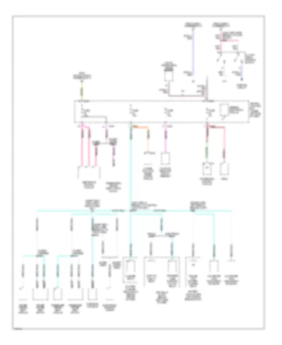
Power Distribution Wiring Diagram (4 of 4) for Ford Pickup F150 2001
List of elements for Power Distribution Wiring Diagram (4 of 4) for Ford Pickup F150 2001:
- (engine harn, left rear of engine compt) s120
- (in seat harness) s300
- (in seat harness) s310
- (main harn, in breakout to central junction box) s228
- (safety belt harn, right side of dash) s311
- 4 wheel anti-lock brake system module
- 4x2 center axle disconnect solenoid
- 4x4 center axle disconnect solenoid
- A/t
- Battery junction box (left side of engine compt)
- Blower/ flasher relay block (behind center of dash)
- C146
- C174
- C242
- C243
- Central junction box (under left side of dash)
- Clutch pedal position switch
- Digital transmission range sensor
- Driver heated seat module
- Driver heated seat switch
- Electronic day/night mirror
- Electronic shift
- Except super crew
- Flasher relay
- From fuse 21 (diagram 2 of 4)
- From ignition switch (diagram 2 of 4)
- Function selector switch assembly
- Fuse 10a
- Fuse 5a
- Generic electronic module
- M/t
- Manual shift
- Nca
- Overhead console
- Passenger heated seat module
- Passenger heated seat switch
- Passenger's air bag deactivation switch
- Powertrain control module
- Radio
- Restraints control module
- Rpo relay block (behind right side of dash)
- Shift on the fly relay
- Starting circuit
- Super crew
- Switch) s227
- Tan/red
- Trailer tow battery charge relay
- Transfer case electric clutch relay

 Čeština
 Dansk
Dansk Deutsch
 Ελληνικά
 English
 Español
 Suomi
Suomi Français
 Français
 עברית
עברית Hrvatski
 Magyar
 Italiano
 日本語
日本語 한국어
한국어 Nederlands
 Polski
 Português
 Português
 Română
 Русский
 Slovenčina
 Slovenščina
 Svenska
 Türkçe
 中文 (中国)