POWER DISTRIBUTION
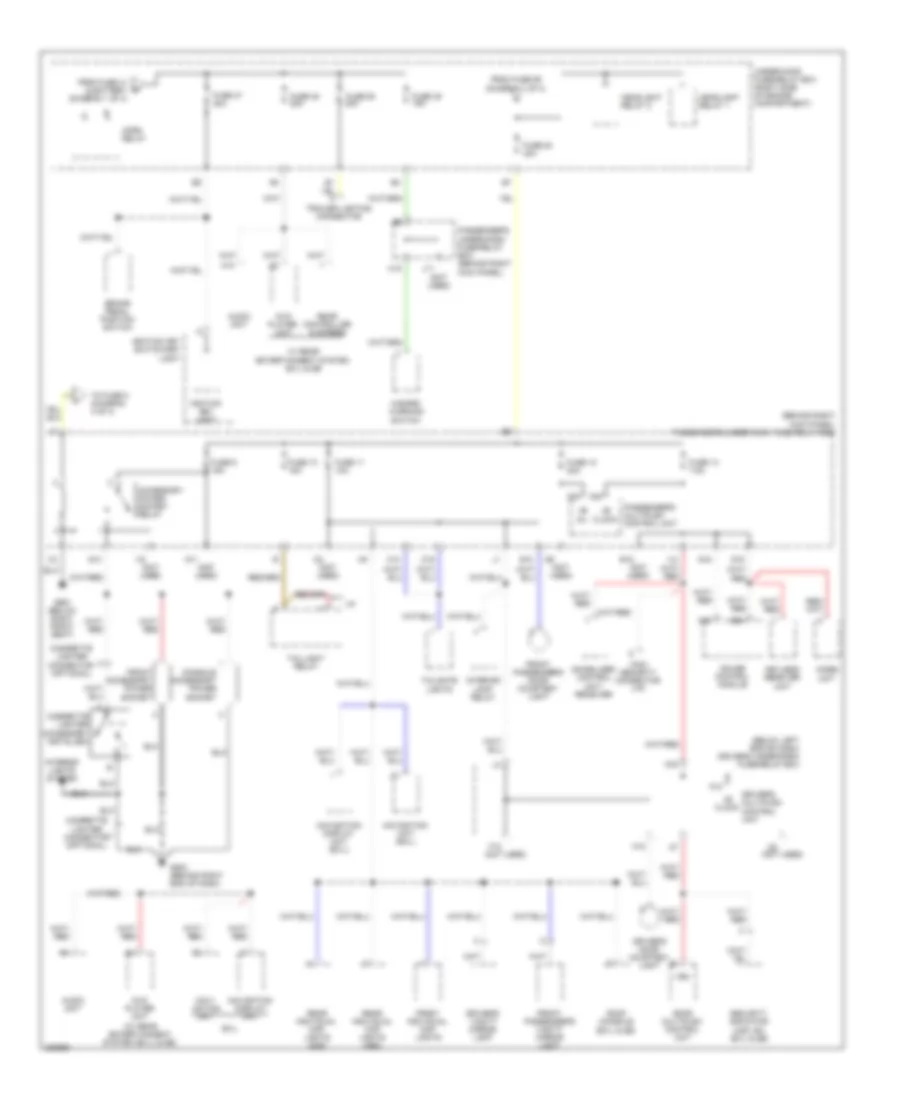
Power Distribution Wiring Diagram (1 of 4) for Honda Pilot EX 2008
 https://portal-diagnostov.com/license.html
Automotive Electricians Portal FZCO
Automotive Electricians Portal FZCO
https://portal-diagnostov.com/license.html
https://portal-diagnostov.com/license.html
Automotive Electricians Portal FZCO
Automotive Electricians Portal FZCO
List of elements for Power Distribution Wiring Diagram (1 of 4) for Honda Pilot EX 2008:
- (behind right kick panel) passenger's under-dash fuse/relay box
- (not used)
- (option connector)
- (right side of engine compartment) under-hood fuse/relay box
- A/c compressor clutch relay
- A/c condenser fan relay
- A12
- A17
- Acc
- Alternator
- Battery
- D10
- Data link connector (dlc)
- Door multiplex control unit
- Driver's power seat adjustment switch (usa: ex, ex-l & se)
- Driver's under-dash fuse/relay box (below left end of dash)
- Drl control unit (canada)
- E16
- Electrical load detector (eld) unit
- Ex-l & se
- Front blower motor relay
- Front passenger's power window switch
- Fuse 1 20a
- Fuse 14 7.5a
- Fuse 15 20a
- Fuse 16 20a
- Fuse 2 20a
- Fuse 3 20a
- Fuse 4 20a
- Fuse 41 120a
- Fuse 42 50a
- Fuse 46 15a
- Fuse 5 (not used)
- Fuse 51 40a
- Fuse 52 40a
- Fuse 53 30a
- Fuse 55 30a
- Fuse 56 40a
- Fuse 57 30a
- Fuse 58 30a
- Fuse 59 7.5a
- Fuse 6 10a
- Fuse 7 20a
- Fuse 8 20a
- G10
- G18
- G651 (below right front seat)
- H18
- I10
- Ignition switch
- Left rear power window switch
- Lock
- Moonroof close relay
- Moonroof open relay
- P/w main rly
- Passenger's multiplex control unit
- Pgm-fi main relay 1
- Power window control unit
- Power window relay
- Radiator fan relay
- Rear blower motor relay
- Rear window defogger relay
- Red
- Right rear power window switch
- Run
- Seat heater relay (ex-l)
- Start
- Starter
- Starter solenoid
- T101
- To auxiliary fuse box (diagram 4 of 4)
- To fuse 4 (diagram 2 of 4)
- To fuse 47 (diagram 3 of 4)
- To fuse 54 (diagram 3 of 4)
- To fuse 6 (diagram 2 of 4)
- To fuse 8 (diagram 4 of 4)
- To starter cut relay (diagram 4 of 4)
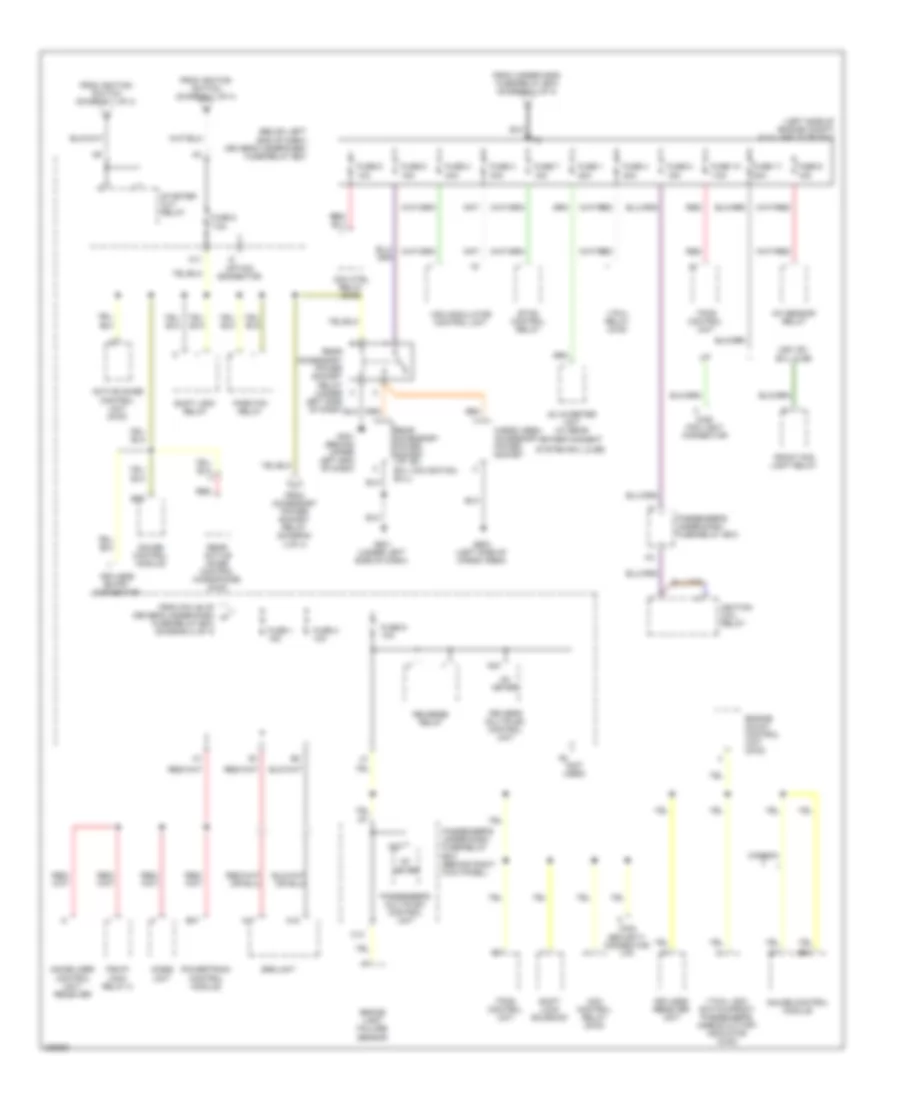
Power Distribution Wiring Diagram (2 of 4) for Honda Pilot EX 2008
List of elements for Power Distribution Wiring Diagram (2 of 4) for Honda Pilot EX 2008:
- (below left end of dash) driver's under-dash fuse/relay box
- (ex, ex-l)
- (ex-l)
- (not used)
- (right front of engine compt)
- (vp)
- A/c compressor clutch relay
- A/c condenser fan relay
- A/c diode assembly
- A/c diode b
- Ac inverter unit (res (dvd): se & ex-l)
- Alternator
- Auxiliary under-hood relay box
- Auxiliary under-hood relay box (right front of engine compt)
- B11
- B13
- Brake pedal position switch
- C17
- C555 option connector
- Climate control unit (usa: ex, ex-l & se)
- Cruise control main switch/vsa off switch
- D11
- D13
- D16
- Drl control unit (canada)
- Electrical compass unit (ex-l w/o navigation)
- Evap canister purge valve
- Fan control relay
- From ignition switch (diagram 1 of 4)
- Front blower motor relay
- Front passenger's airbag cut-off indicator (2wd)
- Front passenger's airbag cut-off indicator/ vtm-4 lock switch (4wd)
- Front washer motor relay
- Fuse 10 7.5a
- Fuse 11 7.5a
- Fuse 12 30a
- Fuse 3 7.5a
- Fuse 4 7.5a
- Fuse 5 10a
- Fuse 6 15a
- Fuse 7 7.5a
- H17
- Hazard warning switch
- Heater control panel (vp)
- Intermittent wiper relay
- J10
- J12
- J15
- Junction connector c104 (rear of engine compt)
- L14
- M13
- M14
- M15
- Ods unit
- Option connector
- Passenger's under-dash fuse/relay box
- Passenger's under-dash fuse/relay box (behind right kick panel)
- Power mirror switch
- Powertrain control module
- Rear blower motor relay
- Rear mode control motor (ex, ex-l, vp & se)
- Rear washer motor relay
- Rear window defogger relay
- Rear window intermittent wiper relay
- Rear window wiper motor
- Recirculation control motor
- Seat heater relay
- To fuse 1 (diagram 4 of 4)
- Under-hood fuse/relay box (right side of engine compt)
- Vsa modulator control unit
- Vtm-4 control unit (4wd)
- Vtm-4 relay (4wd)
- Wind- shield wiper motor
- Wiper/ washer switch
- Wiper/washer switch
Power Distribution Wiring Diagram (3 of 4) for Honda Pilot EX 2008
List of elements for Power Distribution Wiring Diagram (3 of 4) for Honda Pilot EX 2008:
- (behind right kick panel) passenger's under-dash fuse/relay box
- (below left end of dash) driver's under-dash fuse/relay box
- (not used)
- (w/ rear entertainment system (ex-l) & se)
- +b clock
- +b d/l
- A10
- A12
- A23
- A24
- Accessory power socket relay
- Audio unit
- B15
- B24
- Brake pedal position switch
- C10
- C19
- C324 security connector (vp)
- Cigarette lighter (accessory installed)
- Cigarette lighter connector (optional)
- Console accessory power socket
- Door multiplex control unit
- Driver's door courtesy light
- Driver's multiplex control unit
- Driver's vanity mirror light
- Dvd player unit
- E10
- Ex-l
- F12
- From fuse 41 & battery (diagram 1 of 4)
- From fuse 59 (diagram 1 of 4)
- Front accessory power socket
- Front individual map lights
- Front passenger's door courtesy light
- Front passenger's vanity mirror light
- Fuse 10 15a
- Fuse 11 10a
- Fuse 12 20a
- Fuse 13 7.5a
- Fuse 47 20a
- Fuse 48 20a
- Fuse 49 15a
- Fuse 50 20a
- Fuse 54 40a
- Fuse 9 15a
- G11
- G13
- G15
- G16
- G503 (behind right end of dash)
- G651 (below right front seat)
- Gauge control module
- H15
- H18
- Hazard warning switch
- Headlight relay 1
- Headlight relay 2
- Horn relay
- I12
- I16
- Ignition key light
- Ignition key switch/key light
- Immobilizer control unit- receiver
- Imoes unit
- Interior light relay
- Interior lights system
- J11
- Keyless receiver unit
- M19
- Navi- gation unit
- Navigation display unit
- Navigation display unit (ex-l)
- Navigation unit (ex-l)
- Passenger's multiplex control unit
- Passenger's under-dash fuse/relay box (behind right kick panel)
- Rear controller & screen
- Rear individual map lights (2nd)
- Rear individual map lights (3rd)
- Roof console (ex-l & se)
- Security indicator (usa: ex, ex-l & se)
- Tailgate lights
- Taillight relay
- To fuse 8 (diagram 4 of 4)
- Trailer lighting connector
- Under-hood fuse/relay box (right side of engine compartment)
- Vbu
- W/ rear entertainment system ex-l & se
Power Distribution Wiring Diagram (4 of 4) for Honda Pilot EX 2008
List of elements for Power Distribution Wiring Diagram (4 of 4) for Honda Pilot EX 2008:
- (below left end of dash) driver's under-dash fuse/relay box
- (left side of engine compt) auxiliary fuse box
- (not used)
- A/f sensor relay
- A17
- A18
- A22
- A24
- Ac inverter unit (w/ rear
- Acm control relay (2wd)
- Acm ctrl relay (2wd)
- Active noise control unit (2wd)
- B25
- B29
- B37
- Brake light failure sensor
- C13
- C320 fog light connector
- C324 security connector (vp)
- Canada
- Cargo area accessory power socket
- Driver's multiplex control unit
- Engine mount control unit (2wd)
- Entertainment
- Etcs control relay
- From accessory power socket relay (diagram 3 of 4)
- From ignition switch (diagram 1 of 4)
- From pin a5 of driver's under-dash h
- From under-hood fuse/relay box (diagram 1 of 4)
- Front fog light relay
- Fuse 1 15a
- Fuse 1 20a
- Fuse 10 7.5a
- Fuse 11 20a
- Fuse 2 10a
- Fuse 2 40a
- Fuse 3 30a
- Fuse 4 20a
- Fuse 5 10a
- Fuse 6 15a
- Fuse 7 15a
- Fuse 8 15a
- Fuse 8 7.5a
- Fuse 9 10a
- Fuse 9 15a
- Fuse/relay box (diagram 2 of 4)
- G401 (behind upper left end of dash)
- G501 (under left side of dash)
- G602 (left side of cargo area)
- Gauge control module
- Ig1 meter
- Ignition coil relay
- Immobilizer control unit- receiver
- Imoes unit
- Keyless entry connector
- Keyless receiver unit
- M11
- Option connector
- Park pin relay
- Passenger's multiplex control unit
- Passenger's under-dash fuse/relay box
- Passenger's under-dash fuse/relay box (behind right kick panel)
- Pgm-fi main relay 2
- Powertrain control module
- Rear accessory power socket (vp, ex, ex-l navigation, ex-l)
- Rear accessory power socket relay (under left side of dash)
- Rear active noise control microphone (2wd)
- Red
- Reverse relay
- Shift lock relay
- Shift lock solenoid
- Srs unit
- Starter cut relay
- System ex-l & se)
- Tpms control unit
- Usa: ex, ex-l & se
- Vsa modulator control unit
- Vtm-4 lock switch/front passenger's airbag cut-off indicator (4wd)
- Vtm-4 relay (4wd)

 Čeština
 Dansk
Dansk Deutsch
 Ελληνικά
 English
 English
 Español
 Suomi
Suomi Français
 Français
 עברית
עברית Hrvatski
 Magyar
 Italiano
 日本語
日本語 한국어
한국어 Nederlands
 Polski
 Português
 Português
 Română
 Русский
 Slovenčina
 Svenska
 Türkçe
 中文 (中国)