POWER DISTRIBUTION
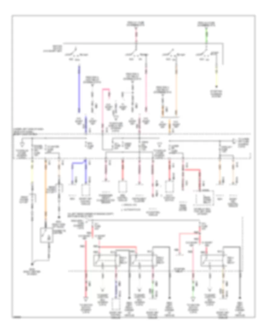
Power Distribution Wiring Diagram (1 of 6) for Hyundai Elantra GT 2013
 https://portal-diagnostov.com/license.html
Automotive Electricians Portal FZCO
Automotive Electricians Portal FZCO
https://portal-diagnostov.com/license.html
https://portal-diagnostov.com/license.html
Automotive Electricians Portal FZCO
Automotive Electricians Portal FZCO
List of elements for Power Distribution Wiring Diagram (1 of 6) for Hyundai Elantra GT 2013:
- (in left rear corner of engine compt)
- (in left rear corner of engine compt) e/r fuse & relay box
- A/c relay (manual a/c)
- A/con fuse 30a
- A/t
- Abs 1 fuse 40a
- Abs 2 fuse 20a
- Alt fuse 150a
- Alternator
- Ams fuse 7.5a
- B+1 fuse 60a
- B+2 fuse 60a
- B+3 fuse 50a
- B/alarm horn relay
- Battery
- Battery & battery fuse box
- Blower fuse 40a
- Blower relay
- Body ground
- Brake switch fuse 10a
- C/fan fuse 40a
- Chg-mk
- Cng-aa
- Cng-ab
- Cng-mk
- Cooling fan (high) relay
- Cooling fan (low) relay
- Deicer fuse 15a
- Deicer relay
- Driver seat warmer module
- E/r fuse & relay box
- E/r-cngb
- E/r-ems
- E29
- Ec01
- Ec02
- Ecm
- Ecu 4 fuse 15a
- Ef31
- Electric parking brake module
- Em11
- Ems box
- Ems fuse 60a
- Engine control relay
- Epb 1 fuse 30a
- Epb 2 fuse 30a
- Esc module
- F/pump fuse 15a
- F/pump relay
- From mdps fuse (diagram 1 of 6)
- From multi fuse (diagram 1 of 6)
- Fs11
- Fs12
- Fs21
- Fuse (diagram 1 of 6)
- Gsl ptc fuse 60a
- Horn fuse 15a
- Horn relay
- Icm relay box (top left side of dash)
- M/t
- M06-b
- M13-b
- Mdps fuse 80a
- Mdps unit
- Mf11
- Mf61
- Multi fuse
- Multipurpose check connector
- Passenger seat warmer module
- Pcm
- Pcm (a/t) ecm (m/t)
- Pnk
- Power
- Ptc relay
- Red
- Rr htd fuse 40a
- Rr htd relay
- S/heater frt fuse 20a
- Seat
- Smart key control module
- Start motor
- Stop lamp switch
- To ems box (diagram 1 of 6)
- To horn
- To ig 1 fuse (diagram 2 of 6)
- To smart junction box (diagram 4 of 6)
- To smart junction box (diagram 5 of 6)
- To smart junction box (diagram 6 of 6)
- W/o
- W/o epb
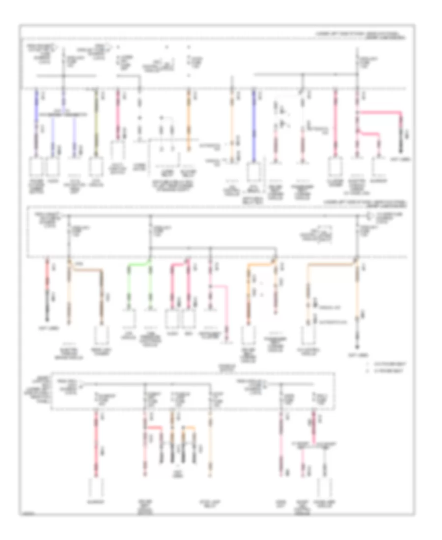
Power Distribution Wiring Diagram (2 of 6) for Hyundai Elantra GT 2013
List of elements for Power Distribution Wiring Diagram (2 of 6) for Hyundai Elantra GT 2013:
- (in left rear corner of engine compt) e/r fuse & relay box
- (or pnk)
- (under left side of dash, near kick panel) smart junction box
- A/bag fuse 15a
- A/bag ind fuse 7.5a
- A/c control module
- Acc
- Automatic a/c
- Bcm
- Bcm fuse 7.5a
- C/lighter fuse 20a
- Cigarette lighter
- Em11
- Em61
- Fr21
- From epb 1 c fuse (diagram 1 of 6)
- From ig 1 fuse (diagram 2 of 6)
- From ig 2 fuse (diagram 2 of 6)
- From pdm 2 (acc) relay (diagram 2 of 6)
- From pdm 3 (ig1) relay (diagram 2 of 6)
- From pdm 4 (ig2) relay (diagram 2 of 6)
- Front power outlet
- Ge01 (left front corner of vehicle)
- Ge02 (left front corner of vehicle)
- Gf04 (right side of trunk)
- Gm02 (right center of dash)
- I/p-a
- I/p-b
- I/p-e
- I/p-f
- I/p-h
- Icm relay box (top left side of dash)
- Ig 1 fuse 20a
- Ig 1 fuse 40a
- Ig 2 fuse 40a
- Ignition switch (w/o smart key)
- Instrument cluster
- Key
- Lock
- M01-w
- M02-a
- M06-b
- M13-a
- M21-a
- M22-b
- Manual a/c
- Mf11
- Module 7 fuse 7.5a
- Multi- function switch
- Nca
- Passenger weight classification sensor
- Pdm 2 (acc) relay
- Pdm 3 (ig1) relay
- Pdm 4 (ig2) relay
- Pnk
- Power outlet frt fuse 15a
- Rear power outlet
- Rear wiper motor
- Rear wiper relay
- Red
- Smart
- Smart key control module
- Srs control module
- Start
- Starter relay
- Starting/ charging system
- To e/r fuse & relay box (diagram 6 of 6)
- To ignition switch (diagram 2 of 6)
- To module 2 fuse (diagram 3 of 6)
- To module 6 fuse (diagram 3 of 6)
- To smart junction box (diagram 2 of 6)
- To wiper frt fuse (diagram 3 of 6)
- W/ smart key
- W/o
- W/o smart key
- Wiper rr fuse 15a
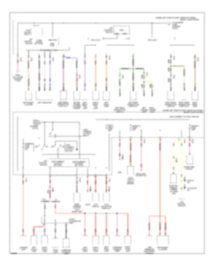
Power Distribution Wiring Diagram (3 of 6) for Hyundai Elantra GT 2013
List of elements for Power Distribution Wiring Diagram (3 of 6) for Hyundai Elantra GT 2013:
- (not used)
- (under left side of dash, near kick panel)
- (under left side of dash, near kick panel) smart junction box
- A/c control module
- A/con fuse 7.5a
- A/v & navigation head unit
- Audio
- Automatic a/c
- Bcm
- Blower relay
- Cluster ionizer
- Console switch
- Driver seat manual switch
- Driver seat warmer module
- E/r fuse & relay box
- E/r fuse & relay box (in left rear corner of engine compt)
- Electric parking brake module
- Electro chromic mirror (w/ home link)
- Em11
- Fd11
- Fd21
- Fr21
- From a/bag ind fuse k (diagram 2 of 6)
- From ips 8 (2ch) r (diagram 5 of 6)
- From module 4 fuse l (diagram 3 of 6)
- From module 7 fuse m (diagram 2 of 6)
- From power outlet frt j fuse (diagram 2 of 6)
- Fs11
- Fs12
- Fs21
- I/p-a
- I/p-b
- I/p-e
- I/p-f
- I/p-h
- Immobilizer module
- Instrument cluster
- Ips control input module
- Ips control start module input
- M01-w
- M02-a
- M09-a
- M09-b
- M13-a
- M15-b
- M21-b
- M22-b
- M26
- Manual a/c
- Mdps fuse 7.5a
- Mdps unit
- Module 2 fuse 7.5a
- Module 3 fuse 7.5a
- Module 4 fuse 7.5a
- Module 5 fuse 7.5a
- Module 6 fuse 10a
- Mr11
- Mts module
- Multi- function switch
- Nca
- On/
- P/seat drv fuse 30a
- Passenger seat warmer module
- Pdm 3 fuse 7.5a
- Pnk
- Power outside mirror switch
- Ptc relay
- Puddle lamp fuse 10a
- Rear view camera
- Red
- Smart junction box
- Smart junction box (under left side of dash, near kick panel)
- Smart key control module
- Stop lamp relay
- Stop lp fuse 15a
- Sunroof
- Sunroof fuse 20a
- Tire pressure monitoring module
- To mdps fuse (diagram 3 of 6)
- W/ navigation
- W/ power seat
- W/ smart key
- W/o navigation
- W/o power seat
- W/o smart key
- Wiper frt fuse 25a
- Wiper motor
- Wiper relay
Power Distribution Wiring Diagram (4 of 6) for Hyundai Elantra GT 2013
List of elements for Power Distribution Wiring Diagram (4 of 6) for Hyundai Elantra GT 2013:
- (under left side of dash, near kick panel)
- A/c control module
- A/t
- A/v & navigation head unit
- Audio
- Automatic a/c
- Aux & usb jack
- Console switch
- Crash pad switch
- Driver safety window module
- Electric chromic mirror (w/o home link)
- Electric parking brake switch
- Fd11
- Fd21
- Fd31
- Fd41
- Ff01
- Fr21
- From ips control module s (diagram 4 of 6)
- From multi fuse (diagram 1 of 6)
- I/p-b
- I/p-d
- I/p-e
- I/p-g
- I/p-h
- Instrument cluster
- Ips 1 (arisu lt, 4ch)
- Ips 1 ctrl
- Ips 7
- Ips 7 ctrl
- Ips control module
- Left rear power window switch
- M01-r
- M09-a
- M15-a
- M21-a
- M22-b
- Manual a/c
- Mem pwr
- Mf11
- Mood lamp
- Mr11
- Multi- function switch
- Nca
- P/wdw lh fuse 25a
- P/wdw rh fuse 25a
- Passenger power outside mirror
- Passenger power window switch
- Pnk
- Power window lh relay
- Power window main switch (w/ safety power window & w/o safety power window & w/ front & rear power windows)
- Power window main switch (w/o safety power window & w/ front power windows)
- Power window rh relay
- Rear view camera
- Red
- Right headlamp
- Right rear combination lamp (out)
- Right rear power window switch
- Smart junction box
- Tail gate relay
- Tgate open fuse 10a
- To ips 7 (diagram 4 of 6)
- W/ navigation
- W/o navigation
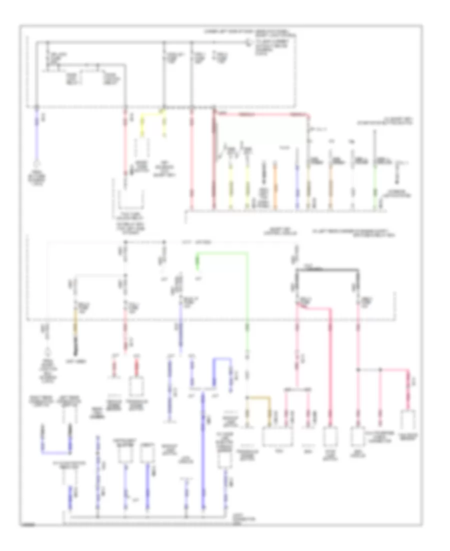
Power Distribution Wiring Diagram (5 of 6) for Hyundai Elantra GT 2013
List of elements for Power Distribution Wiring Diagram (5 of 6) for Hyundai Elantra GT 2013:
- (or nca)
- (under left side of dash, near kick panel)
- (under left side of dash, near kick panel) smart junction box
- (w/o
- A/c control module
- A/v & navigation head unit
- Audio
- Auto light & photo sensor
- Automatic a/c
- Bcm
- Ctrl
- Data link connector
- Door warning switch
- Driver power outside mirror
- Electro chromic mirror (w/ home link)
- Fd11
- Fr11
- Fr21
- From multi fuse (diagram 1 of 6)
- From pdm 2 p fuse (diagram 6 of 6)
- I/p-a
- I/p-b
- I/p-d
- I/p-e
- I/p-f
- I/p-g
- I/p-h
- Immobilizer module
- Instrument cluster
- Interior lamp fuse 10a
- Ips 3
- Ips 3 (1ch)
- Ips 4 (arisu lt, 4ch)
- Ips 8
- Ips 8 (2ch)
- Ips control module
- Ips4 ctrl
- Joint connector jr01
- Leak current autocut device
- Leak current autocut relay
- Leak current autocut rly ctrl
- Leak current autocut sw ctrl
- Leak current autocut switch
- Left front fog lamp
- Left head- lamp
- Left headlamp
- Left license lamp
- Left rear combination lamp (in)
- Left rear combination lamp (out)
- Left room lamp
- Left vanity lamp
- Luggage lamp
- M02-a
- M09-b
- M15-b
- M21-b
- M22-b
- Manual a/c
- Mem pwr
- Memory 1 fuse 7.5a
- Memory 2 fuse 10a
- Mr11
- Mts module
- Multi media fuse 15a
- Nca
- Off
- Overhead console lamp
- Red
- Right front fog lamp
- Right head- lamp
- Right license lamp
- Right rear combination lamp (in)
- Right rear combination lamp (out)
- Right room lamp
- Right vanity lamp
- Room lamp
- Smart junction box
- Smart key)
- Sunroof
- T/ sig sound rly ctrl
- T/sig sound relay
- Tire pressure monitoring module
- To sunroof fuse (diagram 3 of 6)
- W/o
Power Distribution Wiring Diagram (6 of 6) for Hyundai Elantra GT 2013
List of elements for Power Distribution Wiring Diagram (6 of 6) for Hyundai Elantra GT 2013:
- (ill +)
- (ill -)
- (in left rear corner of engine compt)
- (not used)
- (or pnk)
- (or red)
- (under left side of dash, near kick panel)
- (w/ home link) electro chromic mirror
- (w/ smart key) start/stop button switch
- A/t
- A/v & navigation head unit
- Abs 3 fuse 10a
- B/up lp fuse 10a
- Backup lamp switch
- Bcm
- Cng-aa
- Cng-ab
- Cng-mk
- Door lock relay
- Door unlock relay
- Dr lock fuse 20a
- E/r fuse & relay box
- Ec11
- Ecm
- Ecu 3 fuse 10a
- Ecu 6 fuse 15a
- Ef11
- Em11
- Esc module
- Fr21
- From b+3 fuse (diagram 1 of 6)
- From smart junction box (diagram 2 of 6)
- Gm01 (left top dash) panel)
- I/p-d
- I/p-f
- I/p-h
- Icm relay box (top left side of dash)
- Instrument cluster
- Interior lights system
- Joint connector jm04
- Key solenoid (w/o smart key)
- Left rear combination lamp (in)
- M/t
- M02-a
- M06-a
- M13-a
- M13-b
- M13-c
- M15-a
- Mf11
- Module 1 fuse 7.5a
- Mr11
- Mts module
- Multipurpose check connector
- Nca
- Pcm
- Pdm 1 fuse 25a
- Pdm 2 fuse 7.5a
- Pnk
- Rear view camera
- Red
- Right rear combination lamp (in)
- Smart junction box
- Smart key control module
- Sport mode switch
- Ssb amber
- Ssb green
- Ssb ill ground
- Ssb ill power
- Ssb sw 1
- Ssb sw 2
- Stop lamp switch
- Tcu 1 fuse 15a
- To leak current autocut device (diagram 5 of 6)
- Transaxle range switch
- Two turn unlock relay
- Vehicle speed sensor
- Yaw rate sensor

 Čeština
 Dansk
Dansk Deutsch
 Ελληνικά
 English
 Español
 Suomi
Suomi Français
 Français
 עברית
עברית Hrvatski
 Magyar
 Italiano
 日本語
日本語 한국어
한국어 Nederlands
 Polski
 Português
 Português
 Română
 Русский
 Slovenčina
 Slovenščina
 Svenska
 Türkçe
 中文 (中国)