POWER DISTRIBUTION
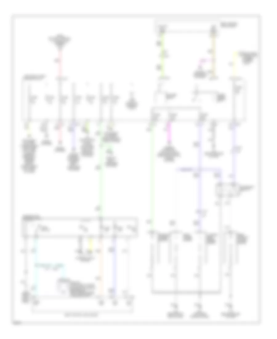
Power Distribution Wiring Diagram (1 of 3) for Infiniti QX56 2011
 https://portal-diagnostov.com/license.html
Automotive Electricians Portal FZCO
Automotive Electricians Portal FZCO
https://portal-diagnostov.com/license.html
https://portal-diagnostov.com/license.html
Automotive Electricians Portal FZCO
Automotive Electricians Portal FZCO
List of elements for Power Distribution Wiring Diagram (1 of 3) for Infiniti QX56 2011:
- (behind left side of dash) m35
- (right rear of engine compt) fuse, fusible link & relay box
- 120v out
- Ac 120v outlet
- Ac 120v outlet main switch
- Air conditioning system
- Anti-lock brakes system
- Anti-theft system
- Bat
- Battery
- Battery terminal w/ fusible link
- Cruise control system
- Defogger system
- E105
- E107
- E201
- Electric brake option connector
- Engine controls system
- Exterior lights system
- F10
- From fuse block j/b (diagram 3 of 3)
- Fuse & fusible holder 6
- Fuse & fusible link holder 2
- Fuse & fusible link holder 3
- Fuse & fusible link holder 4
- Fuse & fusible link holder 5
- Fuse (4wd) 10a
- Fuse (if equiped) 15a
- Fuse (if equiped) 30a
- Fuse (if equipped) 15a
- Fuse (if equipped) 30a
- Fuse (w/ icc) 10a
- Fuse (w/ rear entertainment) 30a
- Fuse 10a
- Fuse 15a
- Fusible link a 140a
- Fusible link b 80a
- Fusible link c 100a
- Fusible link d 80a
- Fusible link e 80a
- Fusible link f 40a
- Fusible link g 40a
- Fusible link h 40a
- Fusible link holder 1
- Fusible link holder 2
- Fusible link i 30a
- Fusible link j (4wd) 30a
- Fusible link k 50a
- Fusible link l 30a
- Fusible link m 50a
- Fusible link n 60a
- Fusible link o 50a
- Fusible link p 50a
- Fusible link q 50a
- Fusible link r 50a
- Fusible link s 30a
- Fusible link t 30a
- Fusible link u (if equiped) 30a
- Fusible link v 30a
- Gnd
- Horns system
- Interior lights system
- Inverter unit
- M35 (behind left side of dash)
- M43 (behind right end of dash)
- M77
- M82
- Navigation & sound systems
- Nca
- Passive restraint system
- Pnk
- Red
- Seats system
- Seats, memory & body computer systems
- Shield
- Starting/ charging system
- Sw ind
- Sw sig
- To fuse block j/b (diagram 2 of 3)
- To fuse block j/b (diagram 3 of 3)
- To ignition relay (diagram 3 of 3)
- To ipdm e/r (intelligent power distribution module engine room) (diagram 3 of 3)
- Transmissions system
- Trunk, tailgate, fuel doors system
- Wiper/ washer system
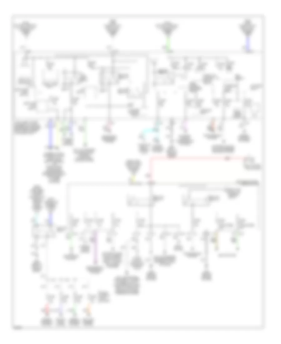
Power Distribution Wiring Diagram (2 of 3) for Infiniti QX56 2011
List of elements for Power Distribution Wiring Diagram (2 of 3) for Infiniti QX56 2011:
- (left end of dash) fuse block j/b
- 10b
- 14f
- 15f e103
- 1b m2
- 8f e103
- Acc ind
- Acc rly cont
- Acce- ssory relay
- Accessory relay 2
- Air conditioning, trunk, tailgate, fuel doors, seats & navigation systems
- B57 (left rear quarter panel)
- Blower relay
- Body control module (bcm)
- Console power socket
- Cpu
- Cruise control, exterior lights & body computer systems
- E101
- E103
- E105
- E17
- Fam mtr rly cont
- From battery terminal w/ fusible link (diagram 1 of 3)
- From fuse & fusible link holder 4 (diagram 1 of 3)
- Front power socket
- Fuse 10a
- Fuse 15a
- Fuse 20a
- Ill ind
- Instrument cluster & computer data lines systems
- Instrument cluster, wiper/washer, computer data lines, passive restraint, warning, mirrors, seats, door locks & anti-theft systems
- Interior lights system
- Ipdm e/r (intelligent power distribution module engine room) (right rear corner of engine compt)
- Lock ind
- Luggage room power socket
- M1 1a
- M19
- M2 7b
- M3 7c
- M35 (behind left side of dash)
- M43 (behind right end of dash)
- M71
- M76 (behind center of dash)
- M77
- Mirrors, navigation, air conditioning, engine controls & sound systems
- On ind
- Push sw
- Push switch
- Push-button ignition switch
- Rear console power socket
- Red
- Seats & body computer systems
- Sound & navigation systems
- Sound systems
- To fuse block j/b (diagram 3 of 3)
Power Distribution Wiring Diagram (3 of 3) for Infiniti QX56 2011
List of elements for Power Distribution Wiring Diagram (3 of 3) for Infiniti QX56 2011:
- (left end of dash) fuse block j/b
- 10f e103
- 10g e104
- 11c
- 11g
- 12c m3
- 2a m1
- 2g e104
- 4b m2
- 4f e103
- A/c relay
- Air conditioning system
- Air conditioning, sound, mirrors, navigation & trunk, tailgate, fuel doors systems
- Anti-lock brakes system
- Anti-lock brakes, cruise control & exterior lights systems
- Anti-lock brakes, cruise control, warning, navigation & sound systems
- Anti-lock brakes, instrument cluster, exterior lights, computer data lines, seats, warning & electronic power steering systems
- Body control module (bcm)
- Cooling fans system
- Cpu
- E10
- E102
- E11
- E14
- E15
- E21 (right front of engine compt)
- Ecm relay
- Electronic suspension system
- Engine controls system
- Engine controls systems
- Exterior lights & anti-lock brakes brakes systems
- Exterior lights & transmissions systems
- Exterior lights systems
- From battery terminal w/ fusible link (diagram 1 of 3)
- From fuse block j/b (diagram 2 of 3)
- From fuse, fusible link & relay box (diagram 1 of 3)
- From fusible link holder 1 (diagram 1 of 3)
- From ipdm e/r (intelligent power distribution module engine room) (diagram 3 of 3)
- Front fog lamp relay
- Front wiper hi relay
- Front wiper relay
- Fuse & fusible link holder 1
- Fuse (if equipped) 15a
- Fuse 10a
- Fuse 15a
- Fuse 20a
- Fuse 30a
- Headlamp high relay
- Headlamp low relay
- Ign rly
- Ignition relay
- Ignition relay 1
- Ignition relay 2
- Ignition relay 3
- Injector relay
- Intelligent power distribution module engine room (ipdm e/r) (right rear corner of engine compt)
- Interior lights system
- Interior lights, exterior lights, headlights, seats, mirrors, air conditioning, navigation, transmissions, engine controls & instrument cluster systems
- M3 10c
- M3 6c
- M3 7c
- M71
- M76 (behind center of dash)
- Rear window defogger relay
- Red
- Seats system
- Starter control relay
- Starter relay
- Steering lock relay
- Tail lamp relay
- Throttle control motor relay
- To ac 120v output main switch (diagram 1 of 3)
- To ignition relay (diagram 3 of 3)
- Transmissions system

 Čeština
 Dansk
Dansk Deutsch
 Ελληνικά
 English
 Español
 Suomi
Suomi Français
 Français
 עברית
עברית Hrvatski
 Magyar
 Italiano
 日本語
日本語 한국어
한국어 Nederlands
 Polski
 Português
 Português
 Română
 Русский
 Slovenčina
 Slovenščina
 Svenska
 Türkçe
 中文 (中国)