POWER DISTRIBUTION
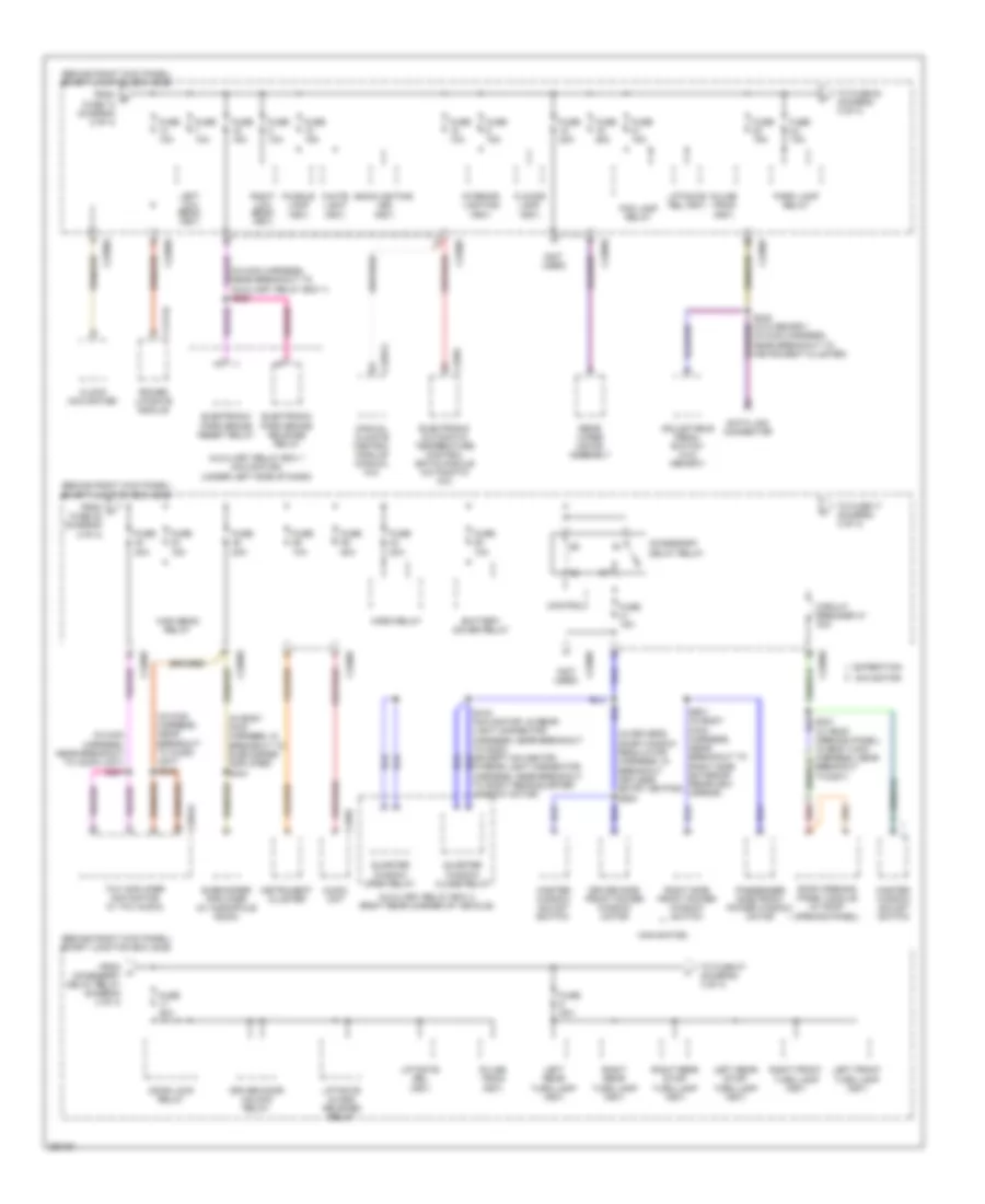
Power Distribution Wiring Diagram (1 of 4) for Lincoln Navigator 2007
 https://portal-diagnostov.com/license.html
Automotive Electricians Portal FZCO
Automotive Electricians Portal FZCO
https://portal-diagnostov.com/license.html
https://portal-diagnostov.com/license.html
Automotive Electricians Portal FZCO
Automotive Electricians Portal FZCO
List of elements for Power Distribution Wiring Diagram (1 of 4) for Lincoln Navigator 2007:
- (center front of engine compartment) battery junction box (bjb)
- (in alternator rectifier system harness, near breakout to battery) s145
- (in alternator rectifier system harness, near breakout to battery) s146
- (in engine control sensor harness, near breakout to battery junction box) s112
- 6r75 automatic transmission (expedition) 6hp26 automatic transmission (navigator)
- Abs control module
- Air suspension compressor relay
- Air suspension module
- Auxiliary relay box 2 (right rear corner of vehicle)
- Battery
- Battery charge trailer tow relay
- Brake pedal position switch
- C175b
- C2131a
- C281b
- C3265a
- C3313b
- C4174a
- Climate controlled seat module
- Console 1 power point
- Evap canister vent solenoid
- Four wheel drive control module
- From a fuse 7 (diagram 1 of 4)
- From b fuse 29 (diagram 1 of 4)
- Fuse (expedition) 20a
- Fuse 10a
- Fuse 15a
- Fuse 20a
- Fuse 25a
- Fuse 30a
- Fuse 40a
- Fuse 50a
- Fuse 60a
- G107 (right rear of engine compartment)
- G301 (on left "b" pillar)
- Generator
- Left third row folding seat relay
- Nca
- Parking lamp trailer tow relay
- Power fold running board module (navigator)
- Power liftgate module
- Powertrain control module (pcm)
- Rear blower motor relay 1
- Rear window defrost relay
- Red
- Right power seat switch
- Right third row folding seat relay
- Run/ start relay
- S102
- S104 red (in engine control sensor harness, near breakout to c140)
- S121 (in engine control sensor harness, under battery junction box)
- S144 (in alternator rectifier system harness, near breakout to battery)
- S328 (in power seats harness, near breakout to climate controlled seat module)
- Starter motor
- To fuse 1 (diagram 2 of 4)
- To fuse 31 (diagram 1 of 4)
- To fuse 41 (diagram 2 of 4)
- To fuse 67 (diagram 4 of 4)
- To fuse 8 (diagram 1 of 4)
- To s258 (diagram 4 of 4)
- Trailer electronic brake control module
- W/ 10-way power seat
- W/ 6-way power seat
Power Distribution Wiring Diagram (2 of 4) for Lincoln Navigator 2007
List of elements for Power Distribution Wiring Diagram (2 of 4) for Lincoln Navigator 2007:
- (behind right kick panel) smart junction box (sjb)
- (center front of engine compartment) battery junction box (bjb)
- (in console panel harness, in breakout to c314) (w/ satellite radio receiver & w/o dvd player) s346
- (not used)
- 3rd row seat enable (fet)
- A/c clutch relay
- Auxiliary audio module
- Bsi (fet)
- C2280e
- C341a
- C341c
- Console 2 power point (navigator)
- Driver seat module
- Driver seat module (w/ 10-way power seat & memory)
- Driver side front power window motor (navigator)
- Dvd player
- Exterior rear view mirror swith
- From d fuse 48 (diagram 2 of 4)
- From fuse 46 (diagram 1 of 4)
- From r s104 (diagram 1 of 4)
- Front blower motor relay
- Front cigar lighter
- Fuel pump relay
- Fuse 10a
- Fuse 15a
- Fuse 20a
- Fuse 25a
- Fuse 30a
- Fuse 40a
- Fuse 7.5a
- G200 (behind right kick panel)
- G301 (on left "b" pillar)
- G402 (navigator: left rear corner of vehicle (except navigator: right rear corner of vehicle)
- Instrument panel power point (expedition)
- Keypad illum (fet)
- Left high intensity discharge headlamp relay (navigator)
- Left power seat switch
- Left power seat switch (w/ memory)
- Left turn trailer tow relay
- Passenger side front power window motor (navigator)
- Pcm power relay
- Rear power point
- Red
- Reversing lamps relay
- Right high intensity discharge headlamp relay (navigator)
- Right turn trailer tow relay
- S120 (in engine control sensor harness, under battery junction box)
- S227
- S419
- Satellite radio receiver
- Starter relay
- To fuse 14 (diagram 3 of 4)
- To fuse 33 (diagram 2 of 4)
- Tpms 1 (fet)
- Tpms 2 (fet)
- Tpms 3 (fet)
- Vbat
- W/ 10-way power seat w/o memory
- W/ 6-way power seat
- Windshield wiper motor assembly
Power Distribution Wiring Diagram (3 of 4) for Lincoln Navigator 2007
List of elements for Power Distribution Wiring Diagram (3 of 4) for Lincoln Navigator 2007:
- (behind right kick panel) smart junction box (sjb)
- (in body main harness, in breakout to subwoofer amplifier) s444
- (in driver's door window regulator harness, in breakout keyless entry keypad) s500
- (in main harness, near breakout to audio unit) s246
- (in main harness, near breakout to audio unit) s247
- (in main harness, near breakout to auxiliary relay box 1) s255
- (navigator)
- (not used)
- Accessory delay relay
- Adjustable pedal switch (w/o memory)
- Audio unit
- Auxiliary relay box 1 (navigator) (under left side of dash)
- Auxiliary relay box 2 (right rear corner of vehicle)
- Backlighting led (fet)
- Battery saver relay
- C2280e
- C2280f
- C2280g
- C228a
- C2357a
- C2364a
- C240a
- C4174a
- Circuit breaker 47 30a
- Clock (navigator)
- Control
- Data link connector
- Door lock relay
- Driver door unlock relay
- Driver side front power window motor
- Electronic automatic temperature control (eatc) module (automatic a/c)
- Electronic park brake release relay
- Electronic park brake reset relay
- Expedition
- Flooor lamp (fet)
- Fog lamp relay
- From s fuse 13 (diagram 2 of 4)
- From t fuse 22 (diagram 3 of 4)
- From u accessory delay relay (diagram 3 of 4)
- Fuse 10a
- Fuse 15a
- Fuse 20a
- Fuse 25a
- High beam relay
- Horn relay
- Instrument cluster
- Interior lighting (fet)
- Left front turn lamp (fet)
- Left low beam (fet)
- Left rear stop/ turn lamp (fet)
- Left rear turn lamp (fet)
- Liftgate glass release relay
- Liftgate rel (fet)
- Manual climate control module (manual a/c)
- Master window adjust switch
- Navigator
- Park lamp relay
- Passenger side front power window motor
- Power liftgate module
- Puddle lamp (fet)
- Pulse train (fet)
- Quarter window close relay
- Quarter window open relay
- Rear wiper motor assembly
- Red
- Right front turn lamp (fet)
- Right low beam (fet)
- Right rear stop/ turn lamp (fet)
- Right rear turn lamp (fet)
- Right side front power window switch
- Roof opening panel module (w/ roof opening panel)
- S248 (w/o memory) (in main harness, near breakout to instrument cluster)
- S321 (w/ roof opening panel) (in body main harness, near breakout to g301)
- S601 (in body main harness, near breakout to right side exterior rearview mirror)
- Subwoofer amplifier (w/ audiophile audio)
- Thx amplifier (navigator w/ thx audio)
- To fuse 17 (diagram 3 of 4)
- To fuse 27 (diagram 4 of 4)
- To fuse 40 (diagram 3 of 4)
- White light (fet)
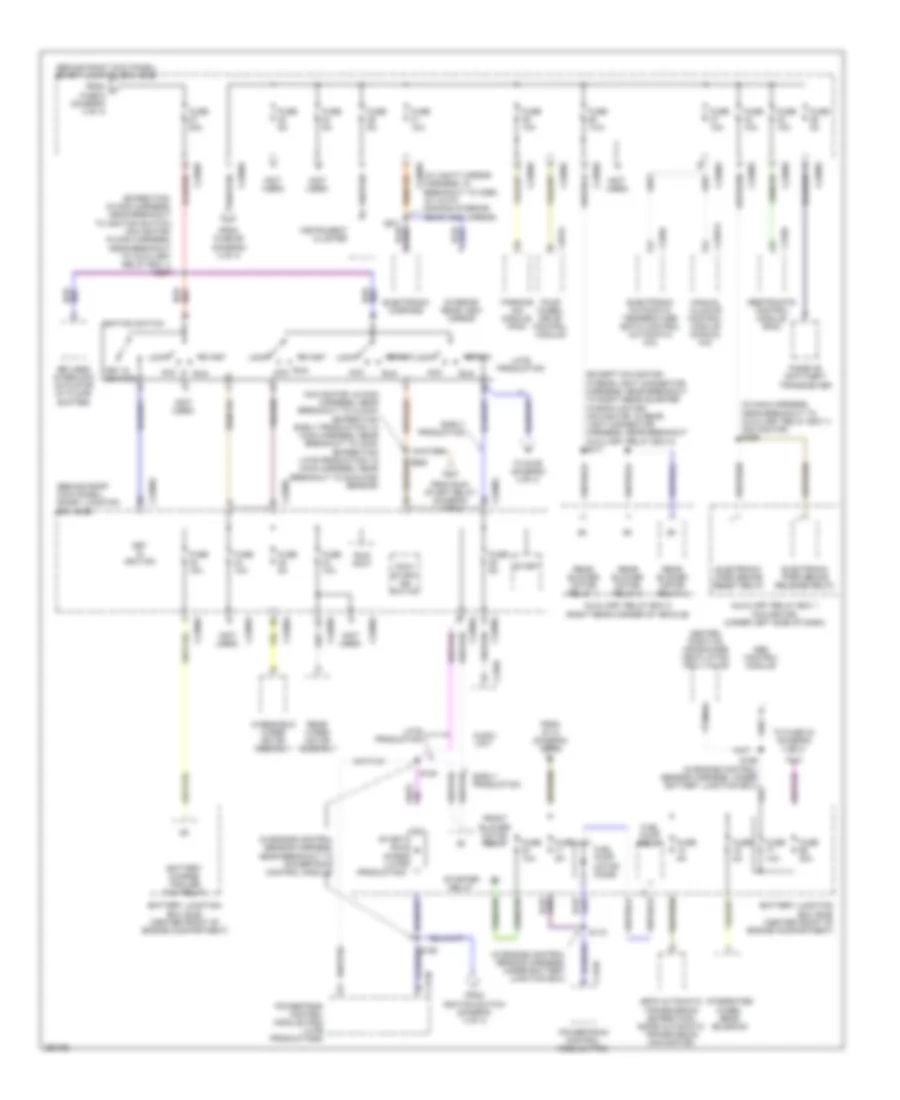
Power Distribution Wiring Diagram (4 of 4) for Lincoln Navigator 2007
List of elements for Power Distribution Wiring Diagram (4 of 4) for Lincoln Navigator 2007:
- (behind right kick panel) smart junction box (sjb)
- (except navigator: in rear light connector harness, near breakout to right rear quarter window motor) (navigator: in rear light connector harness, near breakout auxiliary relay box 2) s417
- (expedition: in main harness, near breakout to ignition switch) (navigator: in main harness, near breakout to auxiliary relay box 1) s257
- (in engine control sensor harness, near breakout to powertrain control module)
- (in engine control sensor harness, under battery junction box)
- (in main harness, near breakout to auxiliary relay box 1) (navigator) s256
- (in vanity mirror harness, in breakout to c298) (w/ auto- dimming interior rear view mirror)
- (navigator: in main harness, near breakout to clock) (expedition early production: in main harness, near breakout to c238) (expedition late production: in main harness, near breakout to sunload sensor)
- (not used)
- 6r75 automatic transmission (expedition) 6hp26 automatic transmission (navigator)
- Abs control module
- Acc
- Audio unit
- Auxiliary relay box 1 (navigator) (under left side of dash)
- Auxiliary relay box 2 (right rear corner of vehicle)
- Battery charge trailer tow relay
- Battery junction box (bjb) (center front of engine compartment)
- C175b
- C2280a
- C2280e
- C2280f
- C2280g
- C228a
- C2357a
- C240a
- C281a
- C310a
- Early production
- Electronic automatic temperature (eatc) control (automatic a/c)
- Electronic compass
- Electronic park brake release relay
- Electronic park brake reset relay
- Four wheel drive control module
- From fuse 69 (diagram 4 of 4)
- From ignition switch (diagram 4 of 4)
- From run/ start relay (diagram 1 of 4)
- From s114 (diagram 1 of 4)
- From v fuse 6 (diagram 3 of 4)
- Front blower motor relay
- Fuel pump motor diode
- Fuel pump relay
- Fuse 10a
- Fuse 20a
- Fuse 30a
- Fuse 5a
- Fuse 7.5a
- Heated positive crankcase ventilation (pcv) valve
- Ignition switch
- Instrument cluster
- Integrated wheel ends solenoid
- Interior rear view mirror
- Key in ignition
- Keyless interlock actuator (w/ floor shifter)
- Late production
- Lock
- Manual climate control module (manual a/c)
- Nca
- Parking aid module (pam)
- Passive anti-theft transceiver
- Powertrain control module (pcm)
- Powertrain control module (pcm) (late productionm)
- Rear blower motor relay 1
- Rear blower motor relay 2
- Rear blower motor relay 3
- Rear wiper motor assembly
- Restraints control module (rcm)
- Run
- Run/ accy
- Run/ start ign switch
- S116
- S154
- S156 (in engine control sensor harness, under battery junction box)
- S258
- S911
- Start
- Start/ run diode (late production)
- Starter relay
- To fuse 30 (diagram 4 of 4)
- To s155 (diagram 4 of 4)
- Windshield wiper motor assembly

 Čeština
 Dansk
Dansk Deutsch
 Ελληνικά
 English
 English
 Español
 Suomi
Suomi Français
 Français
 עברית
עברית Magyar
 Italiano
 日本語
日本語 한국어
한국어 Nederlands
 Polski
 Português
 Português
 Română
 Русский
 Slovenčina
 Slovenščina
 Svenska
 Türkçe
 中文 (中国)