POWER DISTRIBUTION
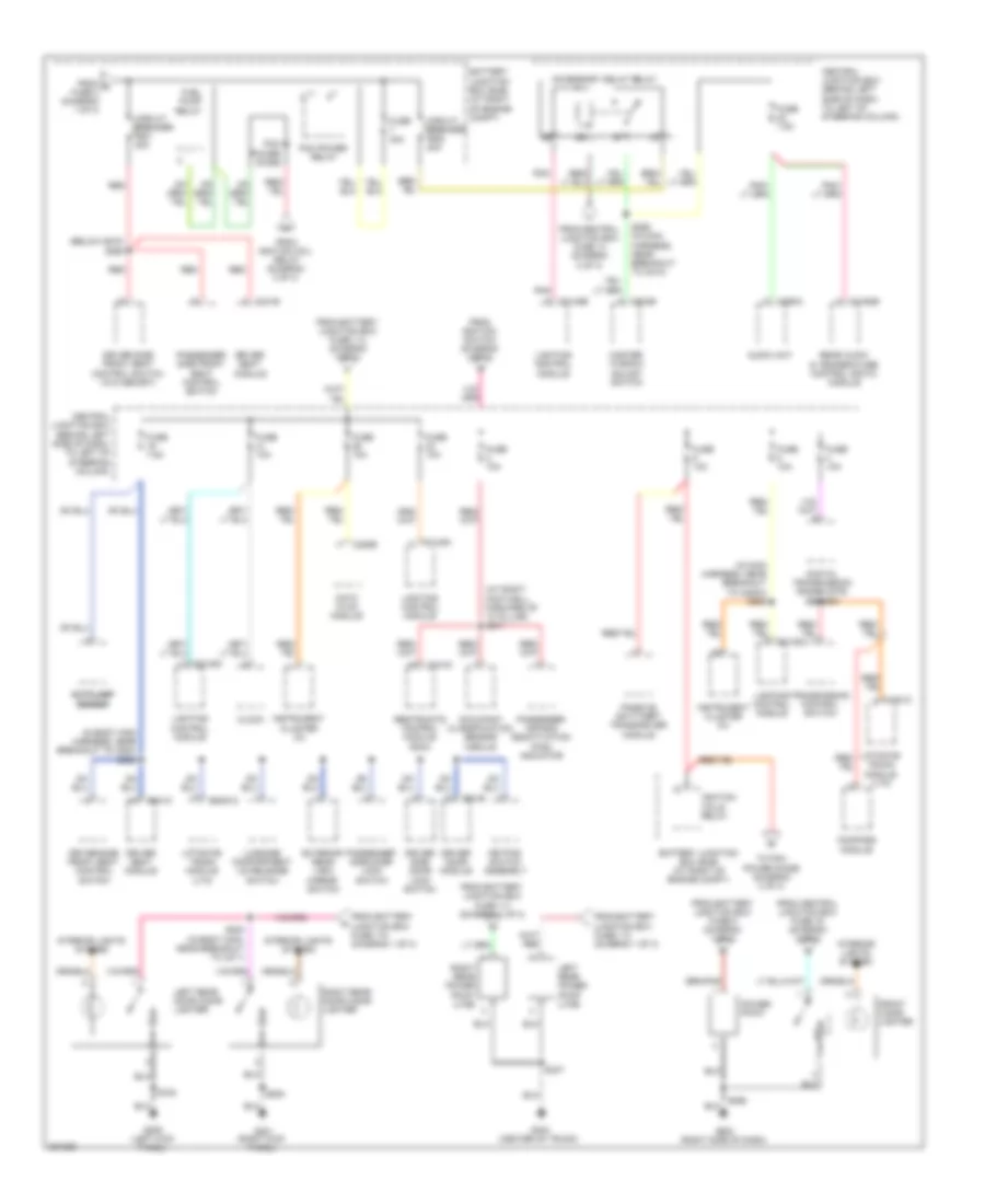
Power Distribution Wiring Diagram (1 of 3) for Lincoln Town Car Executive L 2008
 https://portal-diagnostov.com/license.html
Automotive Electricians Portal FZCO
Automotive Electricians Portal FZCO
https://portal-diagnostov.com/license.html
https://portal-diagnostov.com/license.html
Automotive Electricians Portal FZCO
Automotive Electricians Portal FZCO
List of elements for Power Distribution Wiring Diagram (1 of 3) for Lincoln Town Car Executive L 2008:
- (at right of engine compt) battery junction box (bjb)
- (in body main harness, near breakout to c2131a) s279
- (in body main harness, near breakout to c248) s271
- (in body main harness, near breakout to c4197) s460
- (in body main harness, near breakout to c501b) s501
- (in body main harness, near breakout to c681) s602
- (in dash panel to headlamp junction harness, near breakout to battery junction box (bjb)) s169
- (in dash panel to headlamp junction harness, near breakout to battery junction box) s185
- (in main body harness, breakout to c214) s245
- (starter motor relay & battery ground, near breakout to fusible link a) s162
- A/c clutch relay
- Abs control module
- Air suspension compressor relay
- Battery
- Battery junction box (bjb) (at right of engine compt)
- Blower motor relay
- Brake pedal position switch
- C175b
- C2131a
- C4081d
- C501b
- Deactivator switch
- Driver door module
- Engine cooling fan module
- Evap canister vent control solenoid
- From a fuse 16 (diagram 1 of 3)
- From b fuse 104 (diagram 1 of 3)
- Front heated seat module
- Fuel filler door release switch
- Fuel pump relay
- Fuse 10a
- Fuse 15a
- Fuse 20a
- Fuse 30a
- Fuse 40a
- Fuse 50a
- Generator
- Horn relay
- Ignition coils relay
- Left front lumbar control switch
- Left rear heated seat module (lwb)
- Liftgate/ trunk module (ltm)
- Powertrain control module
- Rear window defrost relay
- Red
- Right front lumbar control switch
- Right rear heated seat module (lwb)
- S136 (in starter motor relay & battery ground harness, near breakout to fusible link a)
- Starter motor
- Starter relay
- Subwoofer amplifier
- To central junction box fuse 10 (diagram 2 of 3)
- To central junction box fuse 20 (diagram 2 of 3)
- To central junction box fuse 25 (diagram 3 of 3)
- To fuse 107 (diagram 1 of 3)
- To fuse 12 (diagram 1 of 3)
- To fuse 601 (diagram 3 of 3)
- To ignition switch (diagram 2 of 3)
- To left rear power point (diagram 3 of 3)
- To power point (diagram 3 of 3)
- To right rear power point (diagram 3 of 3)
- To s200 (diagram 3 of 3)
- Trunk pull-down module
- Vehicle dynamics module
- Windshield wiper motor
Power Distribution Wiring Diagram (2 of 3) for Lincoln Town Car Executive L 2008
List of elements for Power Distribution Wiring Diagram (2 of 3) for Lincoln Town Car Executive L 2008:
- (main harness, near breakout to ignition switch) s255
- A/c cycling switch
- Abs control module
- Acc
- Adjustable pedal switch
- Audio unit
- Auto-dimming view mirror switch
- Breakout to message center switch) s232
- C202a
- C202c
- C2131a
- C2145a
- C2145b
- C2145c
- C2145d
- C228b
- C290a
- Central junction box (behind left side of dash, to left of steering column)
- Data link connector (dlc)
- Datc hvac module
- Digital transmission range (dtr) sensor
- Driver side door lock switch
- Driver side heated seat switch
- Exterior rear view mirror switch
- From battery junction box fuse 1 (diagram 1 of 3)
- From battery junction box fuse 103 (diagram 1 of 3)
- From battery junction box fuse 104 (diagram 1 of 3)
- From ignition switch (diagram 2 of 3)
- Front heated seat module
- Fuse 10a
- Fuse 15a
- Fuse 20a
- Fuse 5a
- Fuse 7.5a
- Ignition switch
- Instrument cluster (ic)
- Key in ignition
- Left rear heated seat module
- Left rear heated seat switch
- Lighting control module
- Lock
- Multi-function switch
- Near breakout to c260) s288
- Parking aid module (pam)
- Passenger side door lock switch
- Passenger side heated seat switch
- Pnk
- Right rear heated seat module
- Right rear heated seat switch
- Run
- S186
- S287
- Start
- To accessory delay relay (diagram 3 of 3)
- To central junction box fuse 2 (diagram 3 of 3)
- To central junction box fuse 7 (diagram 2 of 3)
- To front cigar lighter (diagram 3 of 3)
- Vehicle dynamics module
- W/ limo & livery
- W/o limo & livery
- Windshield wiper motor
Power Distribution Wiring Diagram (3 of 3) for Lincoln Town Car Executive L 2008
List of elements for Power Distribution Wiring Diagram (3 of 3) for Lincoln Town Car Executive L 2008:
- (at right footwell, forward of "a" pillar) s217
- (below s270) s292
- (in body main harness, near breakout to c523)
- (in main harness, near breakout to c220a) s209
- Accessory delay relay
- Audio unit
- Autolamp autolamp sensor sensor
- Battery junction box (bjb) (at right of engine compt)
- C2145a
- C2145b
- C2145c
- C228b
- C290a
- C310a
- C3160b
- C341b
- C341c
- C4081c
- C501b
- C504b
- Central junction box (behind left side of dash, to left of steering column)
- Circuit breaker f601 20a
- Circuit breaker f602 20a
- Clock
- Compass module
- Datc hvac module
- Digital transmission range (dtr) sensor
- Driver door module
- Driver seat module
- Driver side door lock switch
- Driver side front seat control switch
- Driver side front seat control switch (w/o memory)
- Exterior rear view mirror switch
- From battery junction box fuse 111 (diagram 1 of 3)
- From battery junction box fuse 113 (diagram 1 of 3)
- From battery junction box fuse 114 (diagram 1 of 3)
- From battery junction box fuse 115 (diagram 1 of 3)
- From battery junction box fuse 5 (diagram 1 of 3)
- From c fuse 2 (diagram 1 of 3)
- From central junction box fuse 14 (diagram 2 of 3)
- From central junction box fuse 16 (diagram 2 of 3)
- From ignition coil relay (diagram 3 of 3)
- From ignition switch (diagram 2 of 3)
- Front cigar lighter
- Fuel pump relay
- Fuse 10a
- Fuse 30a
- Fuse 7.5a
- G202 (right side of dash)
- G209 (left kick panel)
- G301 (right kick panel)
- G404 (center of trunk)
- Ignition coils relay
- Instrument cluster (ic)
- Interior lights system
- Keypad switch assembly
- Left rear door cigar lighter
- Left rear power point (lwb)
- Liftgate/ trunk module (ltm)
- Lighting control module
- Luggage compartment lid release switch
- Master window adjust switch
- Occupant classification sensor module
- Passenger air bag deactivation (pad) indicator
- Passenger side door lock switch
- Passenger side front seat control switch
- Passive anti-theft transceiver module
- Pcm power diode
- Pcm power relay
- Pnk
- Power point
- Rear audio & temperature control (ratc) module
- Red
- Restraints control module (rcm)
- Right rear door cigar lighter
- Right rear power point (lwb)
- S200 (in body main, near breakout to c211)
- S286 (in main harness, near breakout to c213)
- S298
- S337
- S502
- S700
- S800
- To pcm power diode (diagram 3 of 3)
- Transmission control switch

 Čeština
 Dansk
Dansk Deutsch
 Ελληνικά
 English
 Español
 Suomi
Suomi Français
 Français
 עברית
עברית Hrvatski
 Magyar
 Italiano
 日本語
日本語 한국어
한국어 Nederlands
 Polski
 Português
 Português
 Română
 Русский
 Slovenčina
 Slovenščina
 Svenska
 Türkçe
 中文 (中国)