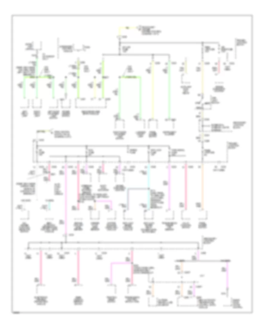
POWER DISTRIBUTION
Power Distribution Wiring Diagram (1 of 3) for Mercury Cougar XR7 1997
 https://portal-diagnostov.com/license.html
Automotive Electricians Portal FZCO
Automotive Electricians Portal FZCO
https://portal-diagnostov.com/license.html
https://portal-diagnostov.com/license.html
Automotive Electricians Portal FZCO
Automotive Electricians Portal FZCO
List of elements for Power Distribution Wiring Diagram (1 of 3) for Mercury Cougar XR7 1997:
- (behind i/p, right side of steering column)
- (eng cntrl sensor harn, right front of engine compt) s124
- (main harn, left rear corner of eng compt) s259
- (not used)
- (window reg harn, left side of trunk)
- (window reg harn, near seat belt switch breakout) s314
- 20a
- Anti- lock brake control module
- Anti- lock power relay (power distribution box)
- Anti- theft in-line fuse
- Anti-lock pump motor relay
- Anti-theft controller module
- Battery
- Brake on/off (boo) switch
- Brake travel switch
- C206
- C208
- C226
- C232
- C233
- C240
- C245
- C258
- C298
- Cigar lighter
- Cigar ltr fuse 20a
- Constant control relay module (ccrm)
- Data link connector (dlc)
- Daytime running lamps (drl) module
- Digital clock
- Driver's seat control switch
- Driver's seat power bolster switch
- Driver's seat power lumbar switch
- Fuse
- Fuse 15a
- Fuse 20a
- Fuse 40a
- Fuse 5a
- Fuse 60a
- G2o5
- Generator/ voltage regulator
- Ground bus
- Horn relay (power distri- bution box)
- Left door lock switch
- Main light switch
- Mega fuse 175a
- Multi-function switch
- Nca
- Obd ii fuse 10a
- Passenger's seat control switch
- Passenger's seat power bolster switch
- Passenger's seat power lumbar switch
- Power antenna module
- Power distribution box
- Powertrain control module (pcm)
- Primary junction block
- Radio
- Radio amplifier
- Rear window defrost switch
- Red
- Remote/keyless entry module
- Right door lock switch
- S123
- S137 (eng cntrl sensor harn, right side of eng compt)
- S202 (main harn, near instrument cluster breakout)
- S204 (main harn, near integrated control module breakout)
- S304
- S402
- Seat/lock circuit breaker 20a
- Secondary junction block
- Semi- automatic temperature control (satc) module
- Starter motor/ solenoid
- Stop/ haz fuse 15a
- Tan/red
- To primary junction block (diagram 3 of 3)
- To splice s100 (diagram 2 0f 3)
- To splice s218 (diagram 2 0f 3)
- Trunk lid release switch
Power Distribution Wiring Diagram (2 of 3) for Mercury Cougar XR7 1997
List of elements for Power Distribution Wiring Diagram (2 of 3) for Mercury Cougar XR7 1997:
- (not used)
- (radio power booster harn, behind center of i/p) s231
- (window reg harn, behind left side of i/p) s305
- (window reg harn, behind left side of i/p) s317
- (window reg harn, left side of trunk) s400
- 3.8l
- 4.6l
- A/c- heater function selector sw
- Acc
- Acc fuse 10a
- Anti- theft controller module
- Blower in-line fuse 30a
- Blower motor speed controller
- C226
- C232
- C233
- C237
- C240
- C250
- C251
- C294
- C298
- Cluster fuse 5a
- Constant control relay module (ccrm)
- Digital clock
- Distribution box) (diagram 1 of 3)
- Driver's right power window switch
- From fuse 17 (power c
- From fuse 9 (power b
- Fuse 20a
- Gnd
- Ignition coil
- Ignition switch
- Instrument cluster
- Instrument cluster system
- Integrated control module
- Left door lock switch
- Left ignition coil
- Left power window switch
- Left radio noise capacitor
- Light sensor/ amplifier
- Lock
- Moonroof electronic control unit
- Nca
- Off
- Power antenna module
- Power distribution box
- Power wdo circuit breaker 20a
- Primary junction block
- Radio
- Radio noise capacitor
- Remote/ keyless entry module
- Right door lock switch
- Right ignition coil
- Right power window switch
- Right radio noise capacitor
- Run
- S100 (dash panel to headlamp harn, left rear of eng compt)
- S121 (fuel charge harn, right rear corner of eng compt)
- S172 (fuel charge harn, near ignition coil breakout)
- S207 (main harn, near brake on/off (boo) switch breakout)
- S209 (main harn, near integrated cntrl module breakout)
- S218
- Secondary junction block
- Speed control amplifier
- Sta
- Start
- To a/c fuse (primary junction block) (diagram 3 of 3)
- Transmission range (tr) sensor
- W/o satc
- W/satc
- Windshield wiper motor
- Wipers fuse 30a
Power Distribution Wiring Diagram (3 of 3) for Mercury Cougar XR7 1997
List of elements for Power Distribution Wiring Diagram (3 of 3) for Mercury Cougar XR7 1997:
- (dash panel to headlamp junction harn, left front of eng compt) s132
- (not used)
- (rear view inside mir harn, near left vanity lamp breakout) s902
- (rear view inside mirror harn, near auto day/night mir breakout)
- A/c fuse 10a
- A/c- heater function selector switch
- Air bag diagnostic monitor
- Air bags fuse 10a
- Anti-lock brake control module
- Anti-lock fuse 10a
- Anti-lock power relay (power distri- bution box)
- Auto- matic day/ night mirror
- Autolamp dual coil relay
- Blend door motor control
- C2007
- C226
- C232
- C233
- C236
- C238
- C240
- C243
- C251
- C258
- C260
- C294
- C295
- C298
- C456
- C457
- Daytime running lamps (drl) module
- Distribution box) (diagram 1 of 3)
- Dome/ map lamps
- Electronic variable orifice (evo) module
- Engine coolant level sensor
- Exterior & interior lights systems
- From fuse 7 (power g
- From ignition switch, pin a4 (diagram 2 of 3)
- Instrument cluster
- Int lps fuse 10a
- Integrated control module
- J/c 1
- Left door courtesy lamp switch
- Left vanity lamp
- Luggage compt lamp
- Main light switch head
- Multi- function switch
- Nca
- Off
- Outside/ recirculate solenoid
- Panel dimmer switch
- Panel lps fuse 5a
- Park
- Park lps fuse 10a
- Power mirror switch
- Primary junction block
- Rear window defrost switch
- Remote/keyless entry module
- Right door courtesy lamp switch
- Right vanity lamp
- Run fuse 5a
- S113 (dash panel to headlamp junct harn, near eng compt fuse panel breakout)
- S237
- S300 (window reg harn, near seat belt switch breakout)
- S901
- Secondary junction block
- Semi- automatic temperature control (satc) module
- Semi-automatic temperature control (satc) module
- Shift lock actuator
- Spare fuse
- Steering wheel rotation sensor
- Traction assist switch
- Transmission control switch (tcs)
- Transmission range (tr) sensor
- Turn signal fuse 10a
- W/ moonroof only
- W/ satc
- W/o rke only
- W/o satc
- Washer fluid level sensor

 Čeština
 Dansk
Dansk Deutsch
 Ελληνικά
 English
 Español
 Suomi
Suomi Français
 Français
 עברית
עברית Hrvatski
 Magyar
 Italiano
 日本語
日本語 한국어
한국어 Nederlands
 Polski
 Português
 Português
 Română
 Русский
 Slovenčina
 Slovenščina
 Svenska
 Türkçe
 中文 (中国)