POWER DISTRIBUTION
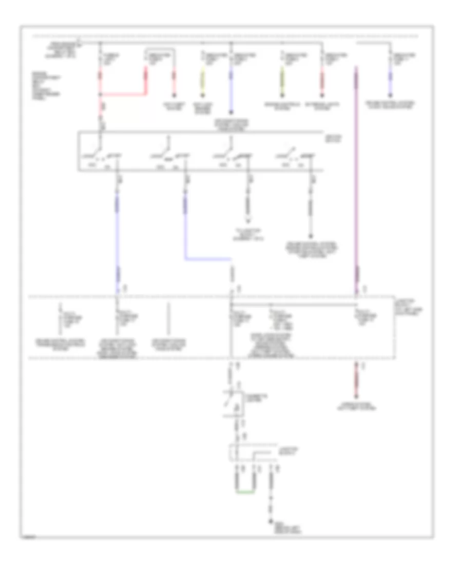
Power Distribution Wiring Diagram (1 of 2) for Mitsubishi Galant LS 1998
 https://portal-diagnostov.com/license.html
Automotive Electricians Portal FZCO
Automotive Electricians Portal FZCO
https://portal-diagnostov.com/license.html
https://portal-diagnostov.com/license.html
Automotive Electricians Portal FZCO
Automotive Electricians Portal FZCO
List of elements for Power Distribution Wiring Diagram (1 of 2) for Mitsubishi Galant LS 1998:
- Air conditioning system
- Air conditioning system, cooling fans system
- Anti-lock brakes system
- Anti-lock brakes system, cruise control system, transmission control system, exterior lights system (stop light)
- Battery
- C34
- C42
- Charging system
- Dedicated fuse 10 15a
- Dedicated fuse 12 10a
- Dedicated fuse 6 10a
- Dedicated fuse 7 10a
- Dedicated fuse 8 10a
- Defogger system
- Door locks system, power windows system
- Door locks system, seats system, power windows system, sound system (w/ power antenna)
- Engine compartment relay box (on right inner fender panel)
- Engine controls system, instrument cluster system
- Exterior lights system (back-up lights)
- From ignition switch (diagram 2 of 2)
- Fusible link 1 100a
- Fusible link 2 60a
- Fusible link 4 50a
- Fusible link 5 30a
- Fusible link 6 40a
- Fusible link 7 30a
- G101 (near eng compt relay box)
- G117 (right rear of engine)
- Headlight relay (on engine compt relay box)
- Headlights system
- Headlights system (fog lights)
- Headlights system, anti- theft system
- Headlights system, exterior lights system, air conditioning system, cruise control system, interior lights system, clock, transmission controls system, warning system, instrument cluster system, sound system, defogger system
- Junction block 1 (at left side kick panel)
- Multi- purpose fuse 11 30a
- Multi- purpose fuse 17 20a
- Multi- purpose fuse 3 10a
- Multi- purpose fuse 4 10a
- Multi- purpose fuse 5 15a
- Multi- purpose fuse 6 30a
- Multi- purpose fuse 8 10a
- Power tops system
- Red
- Starting system
- Taillight relay (on engine compt relay box)
- To fusible link 3 (diagram 2 of 2)
Power Distribution Wiring Diagram (2 of 2) for Mitsubishi Galant LS 1998
List of elements for Power Distribution Wiring Diagram (2 of 2) for Mitsubishi Galant LS 1998:
- (1997) (1998)
- Acc
- Air conditioning system, anti-lock brakes system, door locks system, defogger system
- Air conditioning system, cooling fans system
- Air conditioning system. cooling fans system
- Anti-lock brakes system
- Anti-theft system
- C12
- C13
- C34
- C38
- C41
- C50
- C51
- Cigarette lighter
- Cruise control system, clock, sound system
- Cruise control system, engine controls system, starting system, anti- theft system
- Cruise control system, transmission controls system
- Dedicated fuse 1 30a
- Dedicated fuse 11 15a
- Dedicated fuse 3 30a
- Dedicated fuse 4 10a
- Dedicated fuse 5 20a
- Dedicated fuse 9 10a
- Door locks system (w/ keyless entry), sound system, mirrors system, anti-theft system, wiper/washer system
- Engine compartment relay box (on right inner fender panel)
- Engine controls system
- Exterior lights system
- From engine a compartment relay box (diagram 1 of 2)
- Fusible link 3 30a
- G202 (behind left side of dash)
- Horns system, anti-theft system
- Ignition switch
- Junction block 1 (at left side kick panel)
- Junction block 2
- Lock
- Multi- purpose fuse 12 10a
- Multi- purpose fuse 13 10a
- Multi- purpose fuse 14 15a
- Multi- purpose fuse 15 10a
- Multi- purpose fuse 9 20a 15a
- Nca
- Red
- Start
- To junction block 1 (diagram 1 of 2)

 Čeština
 Dansk
Dansk Deutsch
 Ελληνικά
 English
 English
 Español
 Suomi
Suomi Français
 עברית
עברית Hrvatski
 Magyar
 Italiano
 日本語
日本語 한국어
한국어 Nederlands
 Polski
 Português
 Português
 Română
 Русский
 Slovenčina
 Slovenščina
 Svenska
 Türkçe
 中文 (中国)