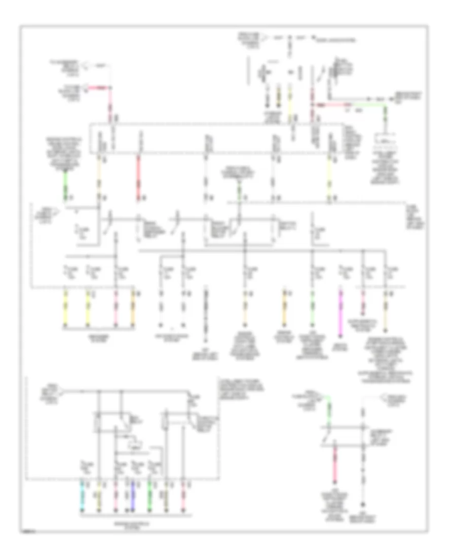
POWER DISTRIBUTION
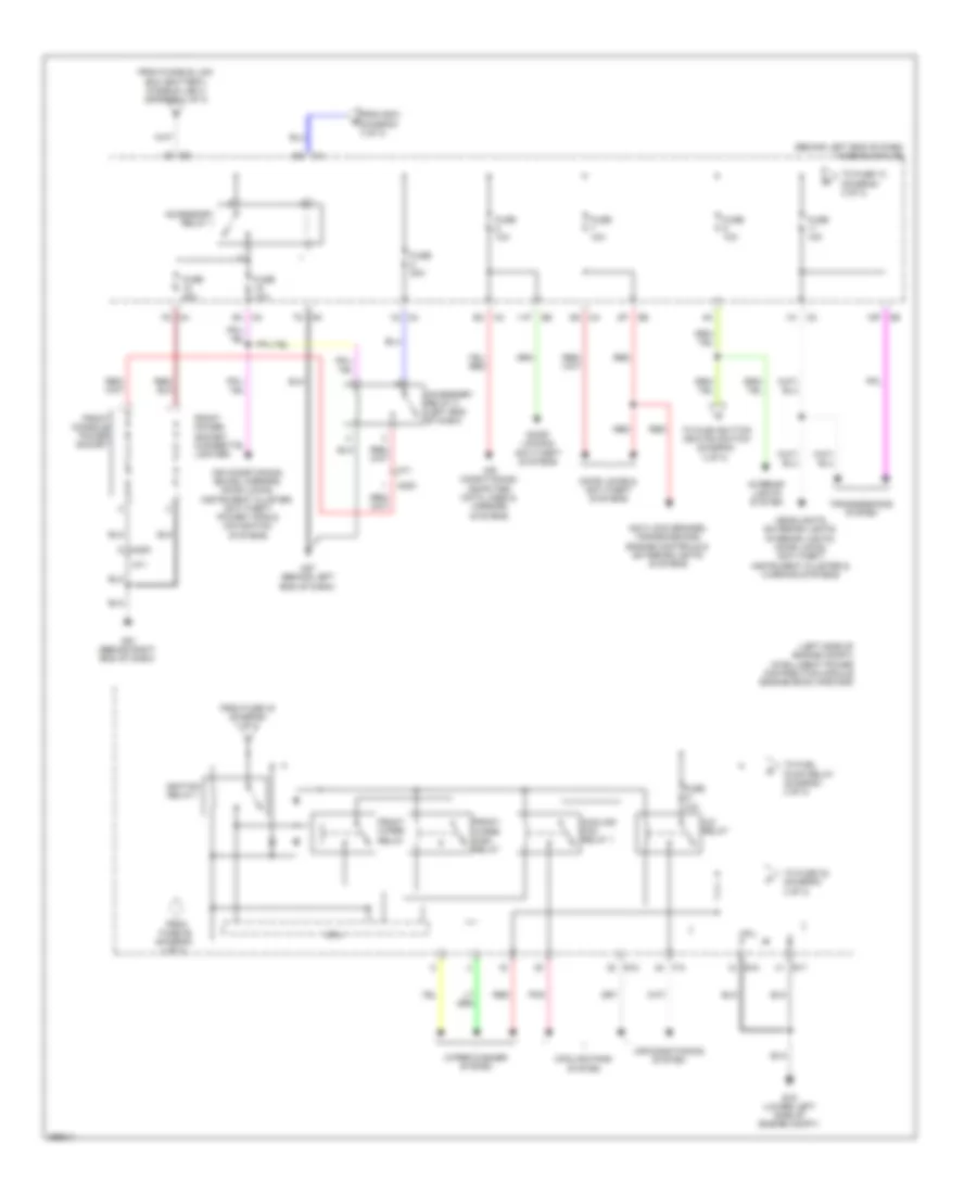
Power Distribution Wiring Diagram, Coupe (1 of 3) for Nissan Altima S 2013
 https://portal-diagnostov.com/license.html
Automotive Electricians Portal FZCO
Automotive Electricians Portal FZCO
https://portal-diagnostov.com/license.html
https://portal-diagnostov.com/license.html
Automotive Electricians Portal FZCO
Automotive Electricians Portal FZCO
List of elements for Power Distribution Wiring Diagram, Coupe (1 of 3) for Nissan Altima S 2013:
- (at battery) fusible link box (battery)
- (left front of engine compt, near ipdm e/r) fuse & fusible link box
- (left side of engine compt) intelligent power distribution module engine room (ipdm e/r)
- 82g
- Anti-lock brakes system
- Battery
- Cooling fans system
- Cpu
- E16
- E18
- E201
- E30
- Ecm relay
- Engine controls system
- Exterior lights system
- F10
- Front fog lamp relay
- Fuse (canada) 10a
- Fuse 10a
- Fuse 15a
- Fuse 30a
- Fusible link a 250a
- Fusible link b 80a
- Fusible link c 100a
- Fusible link d 60a
- Fusible link e 100a
- Fusible link f 50a
- Fusible link g 30a
- Fusible link h 40a
- Fusible link k 40a
- Fusible link l 40a
- Fusible link m 40a
- Headlamp high relay
- Headlamp low relay
- Headlights system
- Horns system
- Interior lights & exterior lights systems
- Joint connector e01 (left side of engine compt)
- Red
- Sound & navigation systems
- Starter relay
- Starting/ charging system
- Tail lamp relay
- Throttle control motor relay
- To bcm (diagram 3 of 3)
- To front wiper relay (diagram 2 of 3)
- To fuse 41 (diagram 2 of 3)
- To fuse block (j/b) (diagram 3 of 3)
- To fuse block (j/b) fuse 5 (diagram 2 of 3)
- W/ bose audio system
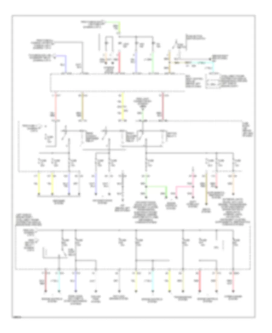
Power Distribution Wiring Diagram, Coupe (2 of 3) for Nissan Altima S 2013
List of elements for Power Distribution Wiring Diagram, Coupe (2 of 3) for Nissan Altima S 2013:
- (behind left end of dash) fuse block (j/b)
- (left side of engine compt) intelligent power distribution module engine room (ipdm e/r)
- 11p
- 12p
- 1q m4
- 1s e7
- 7m m5
- 7q m4
- A/c relay
- Accessory relay 1
- Accessory relay 2 (left end of dash)
- Air conditioning system
- Air conditioning, computer data lines & mirrors systems
- Air conditioning, sound, mirrors, door locks, instrument cluster, anti-theft, power tops & navigation systems
- Anti-lock brakes, transmissions, engine controls & exterior lights systems
- Cooling fan relay 1
- Cooling fans system
- Cpu
- Door locks & anti-theft systems
- E15 (lower left side of engine compt)
- E17
- E18
- F10
- From bcm (diagram 3 of 3)
- From fuse 43 (diagram 1 of 3)
- From fuse 55 (diagram 1 of 3)
- From fusible link box (battery) fusible link c (diagram 1 of 3)
- Front console power socket
- Front power socket (cigarette lighter)
- Front wiper high relay
- Front wiper relay
- Fuse 10a
- Fuse 20a
- Headlights, exterior lights, interior lights, door locks, anti-theft, instrument cluster & warning systems
- Ignition relay 1
- Interior lights system
- M200
- M3 5n
- M57 (behind left end of dash)
- M61 (behind right end of dash)
- M71
- Pnk
- Red
- To fuel pump relay (diagram 3 of 3)
- To fuse 10 (diagram 3 of 3)
- To fuse 32 (diagram 3 of 3)
- To push button ignition switch (diagram 3 of 3)
- Transmissions system
- Wiper/washer system
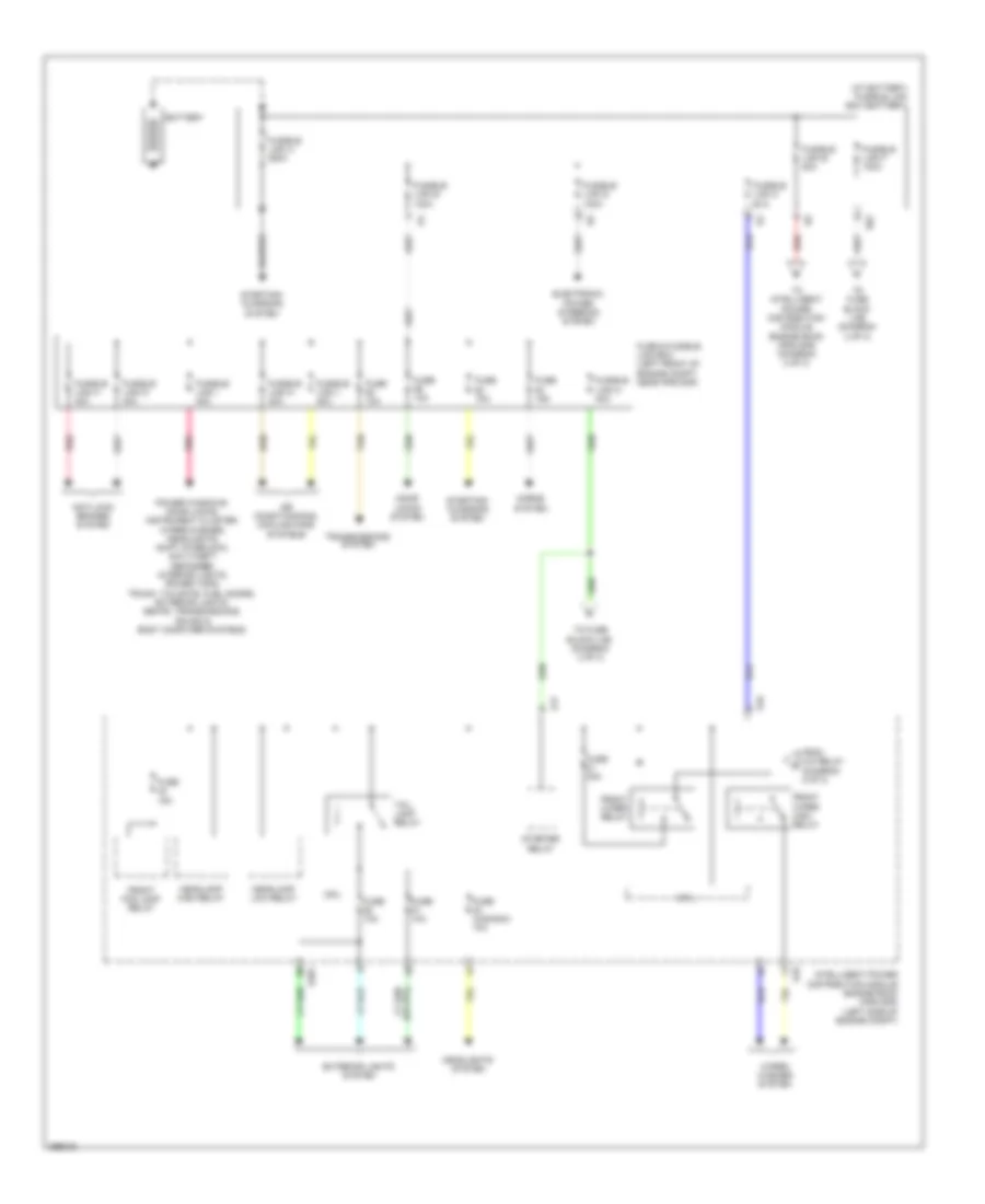
Power Distribution Wiring Diagram, Coupe (3 of 3) for Nissan Altima S 2013
List of elements for Power Distribution Wiring Diagram, Coupe (3 of 3) for Nissan Altima S 2013:
- (behind right end of dash) m61
- (left side of engine compt) intelligent power distribution module engine room (ipdm e/r)
- 10m
- 11m
- 11t
- 12m m5
- 23g
- 29g
- 2n m3
- 4p e6
- 7m m5
- 9m m5
- Acc ind
- Air conditioning system
- Air conditioning, sound, navigation, instrument cluster, transmissions, electronic power steering, mirrors, computer data lines, defogger & warning systems
- Anti-lock brakes system
- B4 10t
- Bcm (body control module) (behind left side of dash)
- Cooling fans system
- Cpu
- Defogger system
- Door locks, anti-theft & starting/charging systems
- E18
- E200
- E30
- Engine controls system
- F10
- From cpu f (diagram 2 of 3)
- From fuse & fusible link box h fusible link h (diagram 1 of 3)
- From fuse 11 d (diagram 2 of 3)
- From fuse block k (j/b) fuse 9 (diagram 2 of 3)
- From g ignition relay 1 (diagram 2 of 3)
- From joint connector e01 (diagram 1 of 3)
- Front blower motor relay
- Fuel pump relay
- Fuse 10a
- Fuse 15a
- Fuse 20a
- Fuse block (j/b) (behind left end of dash)
- Ignition relay 2
- Intelligent power distribution module engine room (ipdm e/r) (left side of engine compt)
- Interior lights system
- Lock ind
- M16
- M17
- M18
- M19
- M21
- M3 8n
- M57 (behind left end of dash)
- On ind
- Pnk
- Push button ignition switch
- Push switch
- Rear window defogger relay
- Red
- Seats system
- Shift interlock system
- To fuse block (j/b) accessory relay (diagram 2 of 3)
- Transmissions system
- Wiper/washer system
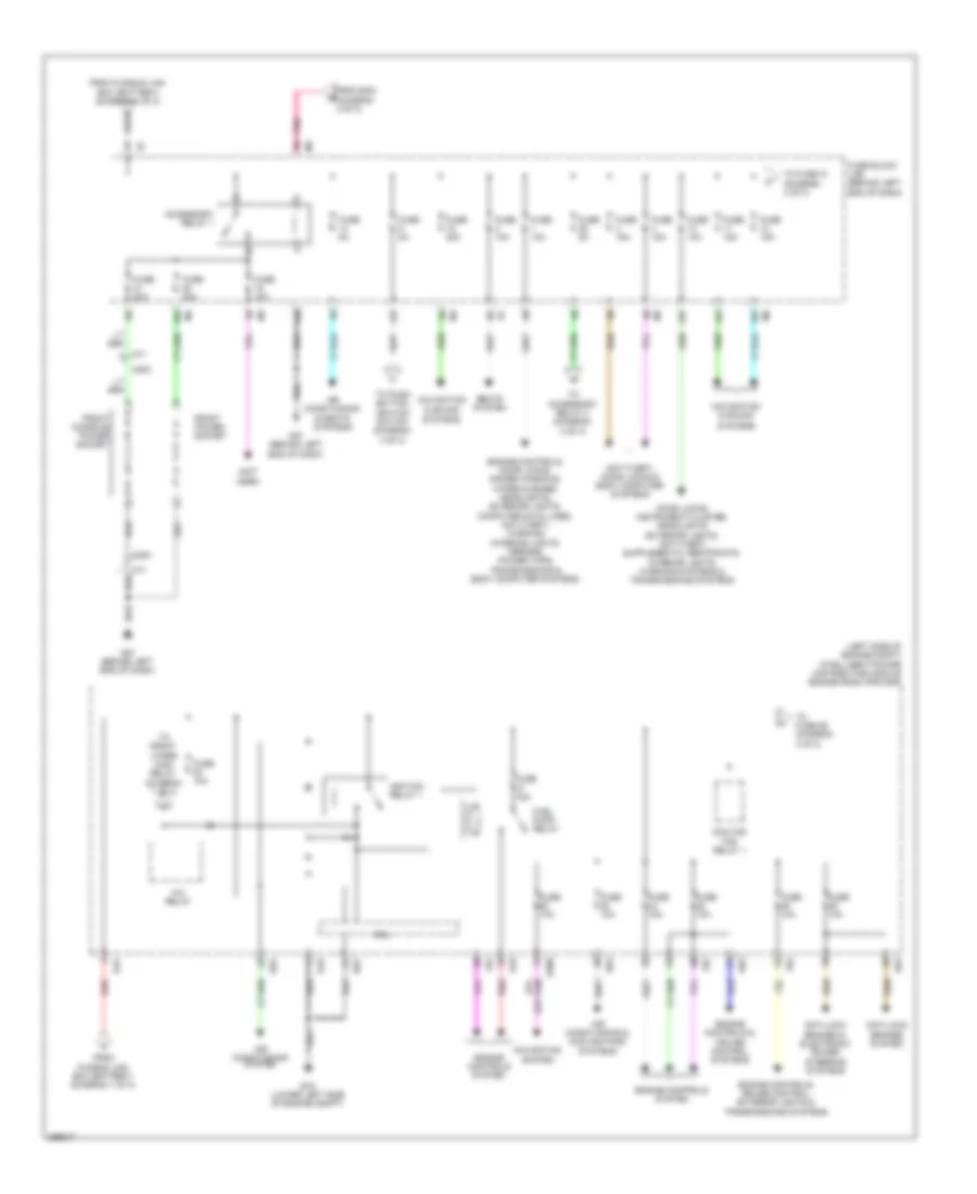
Power Distribution Wiring Diagram, Sedan (1 of 3) for Nissan Altima S 2013
List of elements for Power Distribution Wiring Diagram, Sedan (1 of 3) for Nissan Altima S 2013:
- (at battery) fusible link box (battery)
- Air conditioning & cooling fans systems
- Anti-lock brakes system
- Battery
- Cpu
- Door locks system
- E16
- E17
- E18
- E201
- E62
- Electronic power steering system
- Exterior lights system
- From a/c relay (diagram 2 of 3)
- Front fog lamp relay
- Front wiper high relay
- Front wiper relay
- Fuse & fusible link box (left front of engine compt, near ipdm e/r)
- Fuse (canada) 10a
- Fuse 10a
- Fuse 15a
- Fuse 30a
- Fusible link a 250a
- Fusible link b 100a
- Fusible link c 80a
- Fusible link d 100a
- Fusible link e 80a
- Fusible link f 100a
- Fusible link g 40a
- Fusible link h 40a
- Fusible link i 40a
- Fusible link l 40a
- Fusible link m 40a
- Fusible link n 40a
- Headlamp high relay
- Headlamp low relay
- Headlights system
- Horns system
- Intelligent power distribution module engine room (ipdm e/r) (left side of engine compt)
- Pnk
- Power windows, door locks, instrument cluster, wiper/washer, headlights, shift interlock, anti-theft, defogger, interior lights, power tops, trunk, tailgate, fuel doors, exterior lights, seats, transmissions, sound & body computer systems
- Red
- Starter relay
- Starting/ charging system
- Tail lamp relay
- Tan
- To fuse block (j/b) (diagram 2 of 3)
- To fuse block (j/b) (diagram 3 of 3)
- To intelligent power distribution module engine room (ipdm e/r) (diagram 2 of 3)
- Transmissions system
- Wiper/ washer system
Power Distribution Wiring Diagram, Sedan (2 of 3) for Nissan Altima S 2013
List of elements for Power Distribution Wiring Diagram, Sedan (2 of 3) for Nissan Altima S 2013:
- (left side of engine compt) intelligent power distribution module engine room (ipdm e/r)
- (not used)
- 12r
- 13p
- 13r
- 14p
- 15p
- 16r
- A/c relay
- Accessory relay 1
- Air conditioning & cooling fans systems
- Air conditioning & seats systems
- Air conditioning system
- Anti-lock brakes & electronic power steering systems
- Anti-lock brakes system
- Anti-theft, door locks & body computer systems
- Cooling fan relay 1
- Cpu
- E15 (lower left side of engine compt)
- E16
- E18
- E200
- E63
- Engine controls & cruise control systems
- Engine controls system
- Engine controls, cruise control, exterior lights & transmissions systems
- Engine controls, door locks, power windows, wiper/washer, headlights, exterior lights, computer data lines, anti-theft, warning, interior lights, mirrors, power tops, transmissions & body computer systems
- F83
- F84
- From bcm (diagram 3 of 3)
- From fusible link box (battery) (diagram 1 of 3)
- Front console power socket
- Front power socket
- Fuel pump relay
- Fuse 10a
- Fuse 15a
- Fuse 20a
- Fuse 5a
- Fuse block (j/b) (behind left end of dash)
- Ignition relay 1
- M200
- M57 (behind left end of dash)
- M71
- Navigation & sound
- Navigation system
- Pnk
- Red
- Seats system
- Systems
- To accessory relay 2 (diagram 3 of 3)
- To front wiper high relay (diagram 1 of 3)
- To fuse 10 (diagram 3 of 3)
- To fuse 56 (diagram 3 of 3)
- To push button ignition switch (diagram 3 of 3)
Power Distribution Wiring Diagram, Sedan (3 of 3) for Nissan Altima S 2013
List of elements for Power Distribution Wiring Diagram, Sedan (3 of 3) for Nissan Altima S 2013:
- (behind right end of dash) m61
- (diagram 2 of 3)
- 10r
- 13r
- 16p
- 37g
- Acc led
- Acc rly out
- Acc/on
- Accessory relay 2 (left end of dash)
- Air conditioning system
- Air conditioning, instrument cluster, defogger, mirrors & seats systems
- Air conditioning, instrument cluster, mirrors, navigation & sound systems
- B13
- Bcm (body control module) (behind left side of dash)
- Bwr fan rly out
- Bwr fan rly out m18
- Cpu
- Defogger system
- Door locks system
- E18
- E30
- Ecm relay
- Engine controls system
- Engine controls, computer data lines, navigation & transmissions systems
- Engine controls, cruise control, door locks, exterior lights, shift interlock, anti-theft & transmissions systems
- F83
- F84
- From bcm (diagram 3 of 3)
- From fuse & fusible link box (diagram 1 of 3)
- From fuse 15 f (diagram 2 of 3)
- From fuse block (j/b) i (diagram 2 of 3)
- From fuse block g (j/b) (diagram 2 of 3)
- From ignition relay 1 h
- Front blower motor relay
- Fuse 10a
- Fuse 15a
- Fuse 5a
- Fuse block (j/b) (behind left end of dash)
- Fuse brake sw
- Ignition relay 2
- Illu- mination
- Intelligent power distribution module engine room (ipdm e/r) (left side of engine compt)
- Interior lights system
- M17
- M20
- M57 (behind left end of dash)
- M61 (behind right end of dash)
- Pnk
- Push button ignition switch
- Push switch
- Rear window defogger relay
- Red
- Red eng strt sw no escl
- Rr def rly
- Seats system
- Shorting input m17
- Tan
- Throttle control motor relay
- To accessory relay 2 (diagram 3 of 3)
- To fuse block (j/b) (diagram 2 of 3)

 Čeština
 Dansk
Dansk Deutsch
 Ελληνικά
 English
 Español
 Suomi
Suomi Français
 Français
 עברית
עברית Hrvatski
 Magyar
 Italiano
 日本語
日本語 한국어
한국어 Nederlands
 Polski
 Português
 Português
 Română
 Русский
 Slovenčina
 Slovenščina
 Svenska
 Türkçe
 中文 (中国)