POWER DISTRIBUTION
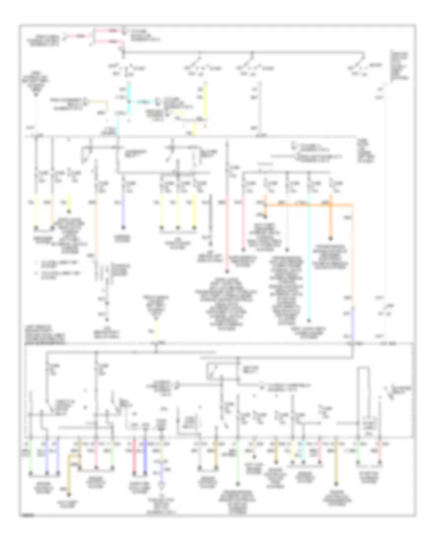
Power Distribution Wiring Diagram (1 of 3) for Nissan Versa S 2013
 https://portal-diagnostov.com/license.html
Automotive Electricians Portal FZCO
Automotive Electricians Portal FZCO
https://portal-diagnostov.com/license.html
https://portal-diagnostov.com/license.html
Automotive Electricians Portal FZCO
Automotive Electricians Portal FZCO
List of elements for Power Distribution Wiring Diagram (1 of 3) for Nissan Versa S 2013:
- (left rear of engine compt) ipdm e/r (intelligent power distribution module engine room)
- A/c comp
- A/c relay
- Air conditioning system
- Battery
- Cooling fan high relay
- Cooling fan low relay
- Cpu
- E10
- E11
- E15 (left rear of engine compt)
- E42
- E44
- E45
- E46
- Exterior lights system
- F/wip hi rly
- F/wip rly
- F39
- F40
- From ignition relay 1 (diagram 2 of 3)
- Front wiper high relay
- Front wiper relay
- Fuse 10a
- Fuse 15a
- Fuse 30a
- Fusible link a 120a
- Fusible link b 60a
- Fusible link box (battery) (on battery (+) terminal)
- Fusible link c 80a
- Fusible link d 100a
- Fusible link e 80a
- Gnd (pwr)
- Gnd (sig)
- H/lp hi
- H/lp lo
- Headlamp high relay
- Headlamp low relay
- Headlights system
- Horn rly
- Horns system
- Interior lights system
- M78
- Nca
- Pnk
- Red
- Starting/ charging system
- Tail lamp relay
- Tail/l rly
- To fuse & fusible link box (diagram 3 of 3)
- To fuse block (j/b) (diagram 2 of 3)
- To ipdm e/r (intelligent power distribution module engine room) (diagram 2 of 3)
- Wiper/washer system
- Wpr autostop
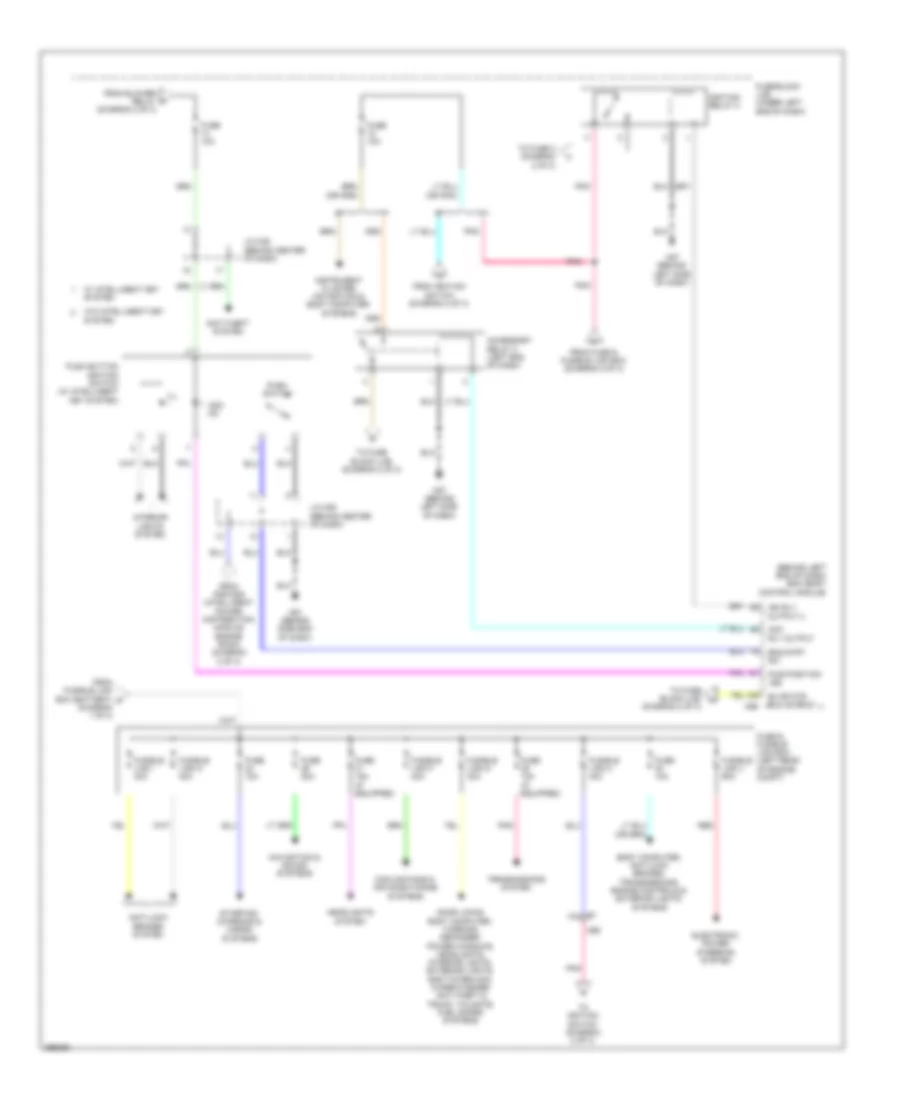
Power Distribution Wiring Diagram (2 of 3) for Nissan Versa S 2013
List of elements for Power Distribution Wiring Diagram (2 of 3) for Nissan Versa S 2013:
- (diagram 1 of 3)
- (diagram 3 of 3)
- (left rear of engine compt) ipdm e/r (intelligent power distribution module engine room)
- 47a e7
- 93a
- Acc
- Accessory relay 1
- Air conditioning system
- Anti-lock brakes system
- Anti-theft system
- Anti-theft, defogger, interior lights, warning, body computer & shift interlock systems
- Blower relay
- Body computer & wiper/washer systems
- Can h
- Can l
- Computer data lines system
- Console power socket
- Cpu
- Defogger system
- Door locks, body computer, anti-lock brakes, transmissions, shift interlock, anti-theft, wiper/washer, warning, engine controls, headlights, exterior lights, instrument cluster, interior lights & electronic power steering systems
- Door locks, body computer, headlights, interior lights, anti-theft, exterior lights & warning systems
- E42
- E43
- E44
- E45
- E46
- E47
- Ecm relay
- Engine controls & cooling fans systems
- Engine controls & transmissions systems
- Engine controls system
- F42
- F43
- From accessory relay 2 k
- From fuse & fusible link box (diagram 3 of 3)
- From fusible link box (battery) (diagram 1 of 3)
- From ignition relay 2 (diagram 3 of 3)
- Fuel pump relay
- Fuse 10a
- Fuse 15a
- Fuse 20a
- Fuse block (j/b) (under left end of dash)
- Ig1
- Ig2
- Ignition relay 1
- Ignition switch (w/o intelli- gent key system)
- M57 (behind left side of dash)
- M69
- M79 (behind right end of dash)
- Mirrors system
- Off
- Pnk
- Push strt sw
- Red
- Start
- Start mtr
- Starter relay
- Starting/ charging system
- Throttle control motor relay
- To front wiper relay (diagram 1 of 3)
- To front wiper relay d
- To fuse 14 (diagram 3 of 3)
- To fuse block (j/b) (diagram 3 of 3)
- To fuse block (j/b) (diagram 3 of 3) from bcm (diagram 3 of 3)
- To push button ignition switch (diagram 3 of 3)
- Transmissions, engine controls, defogger, electronic power steering & sound systems
- Transmissions, exterior lights, engine controls & starting/ charging systems
- W/ intelligent key system
- W/o intelligent key system
Power Distribution Wiring Diagram (3 of 3) for Nissan Versa S 2013
List of elements for Power Distribution Wiring Diagram (3 of 3) for Nissan Versa S 2013:
- (behind left end of dash) bcm (body control module)
- (diagram 2 of 3)
- Acc rly output
- Acc/ on
- Accessory relay 2 (left end of dash)
- Anti-lock brakes system
- Anti-theft system
- Blwr mtr rly output
- Body computer, anti-lock brakes, transmissions, engine controls & exterior lights systems
- Cooling fans & air conditioning systems
- Door locks, body computer, warning, defogger, power windows, headlights, interior lights, exterior lights, shift interlock, wiper/washer, anti-theft & trunk, tailgate, fuel doors systems
- E7 10a
- Electronic power steering system
- Eng strt sw
- From blower relay h
- From fuse & fusible link box (diagram 2 of 3)
- From fusible link box (battery) n (diagram 1 of 3)
- From ignition switch (diagram 2 of 3)
- From ipdm e/r (intelligent power distribution module engine room) (diagram 2 of 3)
- Fuse & fusible link box (left rear of engine compt)
- Fuse 10a
- Fuse 10a (if equipped)
- Fuse 15a (if equipped)
- Fuse 20a
- Fuse block (j/b) (under left end of dash)
- Fusible link f 40a
- Fusible link g 40a
- Fusible link h 40a
- Fusible link i 40a
- Fusible link j 60a
- Fusible link m 40a
- Headlights system
- Ign rly output 2
- Ignition relay 2
- Ill
- Instrument cluster, navigation & body computer systems
- Interior lights system
- J/c m05 (behind center of dash)
- M57 (behind left side of dash)
- M61 (behind side end of dash)
- M69
- M98
- Navigation & sound systems
- Pnk
- Push button ignition switch (w/ intelligent key system)
- Push switch
- Pwr position led
- Red
- Starting/ charging & horns systems
- To fuse 2 (diagram 2 of 3)
- To fuse block (j/b) (diagram 2 of 3)
- To fuse block (j/b) m
- To ignition switch (diagram 2 of 3)
- Transmissions system
- W/ intelligent key system
- W/o intelligent key system

 Čeština
 Dansk
Dansk Deutsch
 Ελληνικά
 English
 Español
 Suomi
Suomi Français
 Français
 עברית
עברית Hrvatski
 Magyar
 Italiano
 日本語
日本語 한국어
한국어 Nederlands
 Polski
 Português
 Português
 Română
 Русский
 Slovenčina
 Slovenščina
 Svenska
 Türkçe
 中文 (中国)