POWER DISTRIBUTION
Power Distribution Wiring Diagram (1 of 5) for Pontiac G6 GT 2005
 https://portal-diagnostov.com/license.html
Automotive Electricians Portal FZCO
Automotive Electricians Portal FZCO
https://portal-diagnostov.com/license.html
https://portal-diagnostov.com/license.html
Automotive Electricians Portal FZCO
Automotive Electricians Portal FZCO
List of elements for Power Distribution Wiring Diagram (1 of 5) for Pontiac G6 GT 2005:
- (not used)
- Abs fuse 24 60a
- Audio amp fuse 13 25a
- Audio amplifier
- Auxiliary power outlet
- Back up lp fuse 17 10a
- Back-up lamp relay 33
- Batt
- Battery
- C12
- Cig/aux fuse 20 20a
- Cigar lighter
- Digital radio receiver (if equipped)
- Driver heated seat control module
- Electronic brake control module (if equipped)
- Eps fuse 41 80a
- From htd b st fuse 14 (diagram 1 of 5)
- G303 (on left front of passenger compt, in back of left front kick panel)
- Generator
- Htd st fuse 14 15a
- Passenger heated seat control module
- Pcm fuse 13 10a
- Power steering control module
- Powertrain control module (pcm)
- Rbec 1 fuse 22 60a
- Rear fuse block (left side of rear compartment, behind left rear wheel well)
- Rear window defogger grid
- Red
- Remote control door lock receiver
- Rke/xm fuse 16 7.5a
- Rr defog fuse 23 30a
- Rr defog relay 26
- Starter solenoid
- Sun rf fuse 10 15a
- Sunroof control module (if equipped)
- To back up lp fuse (diagram 1 of 5)
- To ibcm 2 fuse 25 (diagram 2 of 5)
- Underhood fuse block (in left side of engine compt)
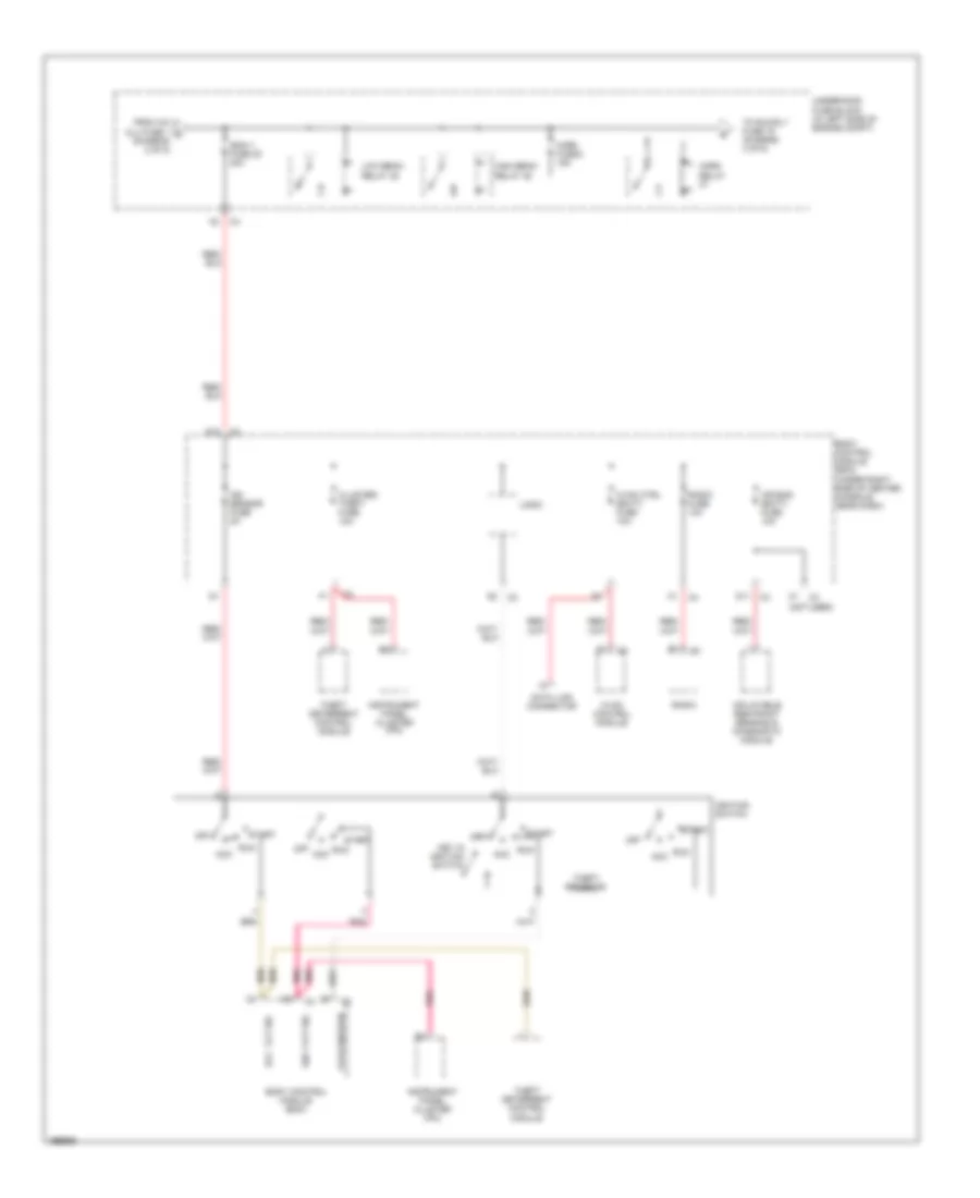
Power Distribution Wiring Diagram (2 of 5) for Pontiac G6 GT 2005
List of elements for Power Distribution Wiring Diagram (2 of 5) for Pontiac G6 GT 2005:
- (if equipped)
- (not
- (under left front seat) s301
- 10a
- A/c clu fuse 1 10a
- A/c clutch relay 34
- Accessory relay
- B11
- Body control module (bcm) (under right side of center console, near dash)
- C/fan 1 fuse 17 30a
- C11
- Cooling fan 1 relay 28
- Cooling ser/par relay 29
- D11
- Door locks fuse 15a
- Driver heated seat control module
- Driver heated seat switch
- Driver window switch
- E11
- Emissions 1 fuse 6 10a
- Etc fuse 2 15a
- Evaporative emission (evap) canister purge solenoid
- From eps a fuse 41 (diagram 1 of 5)
- Heated oxygen sensor (ho2s) bank 1 sensor 1
- Heated oxygen sensor (ho2s) bank 1 sensor 2
- Heated oxygen sensor (ho2s) bank 2 sensor 1
- Heated oxygen sensor (ho2s) bank 2 sensor 2
- Ibcm 2 fuse 25 50a
- Logic
- Mass air flow (maf)/ intake air temperature (iat) sensor
- Nca
- Passenger heated seat control module
- Passenger heated seat switch
- Passenger window switch
- Power windows fuse 30a
- Powertrain control module (pcm)
- Powertrain relay 33
- Rear fuse block
- Rly ctrl
- Roof/heat seat fuse 20a
- Sunroof control module
- Sunroof master control module
- Throttle actuator control (tac) module
- To ibcm 1 fuse 20 (diagram 3 of 5)
- To interior lights fuse (diagram 4 of 5)
- Under- hood fuse block (in left side of engine compt)
- Used)
- W/ panoramic sunroof
- W/ standard sunroof
- Windshield wiper/ washer switch
- Wiper sw fuse 10a
Power Distribution Wiring Diagram (3 of 5) for Pontiac G6 GT 2005
List of elements for Power Distribution Wiring Diagram (3 of 5) for Pontiac G6 GT 2005:
- (not used)
- Acc vlt sig
- Air bag (batt) fuse 10a
- Body control module (bcm)
- Body control module (bcm) (under right side of center console, near dash)
- Cluster/ theft fuse 10a
- D11
- D12
- Data link connector
- From a/c clu fuse 1 c (diagram 2 of 5)
- High beam relay 35
- Horn fuse 8 15a
- Horn relay
- Hvac control module
- Hvac ctrl (batt) fuse 10a
- Ibcm 1 fuse 20 30a
- Ign 1 vlt sig
- Ign sensor fuse 2a
- Ignition switch
- Inflatable restraint sensing & diagnostic module
- Instrument panel cluster (ipc)
- Key in ignition switch
- Logic
- Low beam relay 38
- Off
- Off/crnk/run
- Pnk
- Radio
- Radio fuse 10a
- Run acc
- Start
- Theft deterrent control module
- Theft resistor
- To run rly fuse 19 (diagram 4 of 5)
- Underhood fuse block (in left side of engine compt)
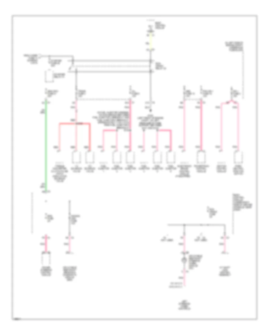
Power Distribution Wiring Diagram (4 of 5) for Pontiac G6 GT 2005
List of elements for Power Distribution Wiring Diagram (4 of 5) for Pontiac G6 GT 2005:
- (left side of rear compartment, behind left rear wheel well) rear fuse block
- (not used)
- Adjustable pedal module (if equipped)
- Adjustable pedal position switch (if equipped)
- Body control module (under right side of center console, near dash)
- C/fan 2 fuse 18 30a
- Cooling fan 2 relay 30
- D10
- Driver seat adjuster switch
- Drv st fuse 2 30a
- E10
- Emission 2 fuse 5 10a
- Evaporative emission (evap) canister vent solenoid valve
- From door d locks fuse (diagram 2 of 5)
- From horn fuse 8 e (diagram 3 of 5)
- Frt fog lp fuse 10 10a
- Frt fog relay
- Fuel fuse 25 15a
- Fuel relay
- Hvac blower fuse 20a
- Hvac blower high relay
- Hvac control module
- Hvac ctrl (ign) fuse 10a
- Inadvertent power outlet relay
- Interior lights fuse 10a
- Logic
- Onstar fuse 10a
- Outside rearview mirror switch
- Park lps fuse 6 10a
- Park lps relay
- Pedal fuse 10a
- Power mirrors fuse 2a
- Rbec 2 fuse 23 60a
- Rly ctrl
- Run relay
- Run rly fuse 19 30a
- Stop lp fuse 44 10a
- Stop lp relay 45
- To run crank relay 32 (diagram 5 of 5)
- Trunk fuse 22 10a
- Trunk relay
- Underhood fuse block (in left side of engine compt)
- Vehicle communication interface module (if equipped)
- Wiper 1 relay
- Wiper fuse 14 25a
Power Distribution Wiring Diagram (5 of 5) for Pontiac G6 GT 2005
List of elements for Power Distribution Wiring Diagram (5 of 5) for Pontiac G6 GT 2005:
- (if equipped)
- (in fuel injector harness, on main branch between fuel injector 3 breakout and fuel injector 2 breakout, approximately 4 cm (1.6 in) from fuel injector 2 breakout) s130
- (in left side of engine compt) underhood fuse block
- (not used)
- (w/ uk 3)
- (w/o uk 3)
- 1-2 solenoid valve
- 2-3 solenoid valve
- A/t shift lock control assembly
- Abs fuse 15 10a
- Air bag (ign) fuse 10a
- B10
- Body control module
- Body control module (under right side of center console, near dash)
- C10
- Electronic brake control module
- Eps fuse 2a
- From wiper fuse 14 (diagram 4 of 5)
- Fuel injector
- G109 (left front of engine compt, on left rear side of core support, between g101 and g104)
- Ibcm (r/c) fuse 21 30a
- Ign 1 fuse 3 15a
- Ignition control module
- Inflatable restraint sensing & diagnostic module (sdm)
- Inflatable restraint steering wheel module coil
- Inj fuse 5 10a
- Left steering wheel controls
- Park/ neutral position switch
- Pcm ign 1 fuse 16 10a
- Pnk
- Power steering control module
- Powertrain control module
- Red
- Rly hi ctrl
- Run crank fuse 2a
- Run/ crank relay 32
- S103
- Starter fuse 26 30a
- Starter relay 31
- Torque converter clutch pulse width modulation solenoid valve
- Trans fuse 4 10a

 Čeština
 Dansk
Dansk Deutsch
 Ελληνικά
 English
 Español
 Suomi
Suomi Français
 Français
 עברית
עברית Hrvatski
 Magyar
 Italiano
 日本語
日本語 한국어
한국어 Nederlands
 Polski
 Português
 Português
 Română
 Русский
 Slovenčina
 Slovenščina
 Svenska
 Türkçe
 中文 (中国)