POWER DISTRIBUTION
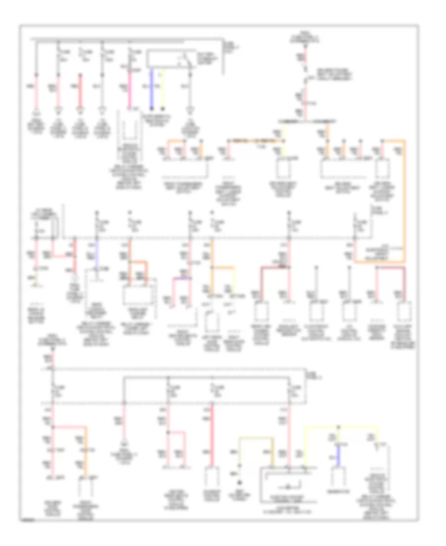
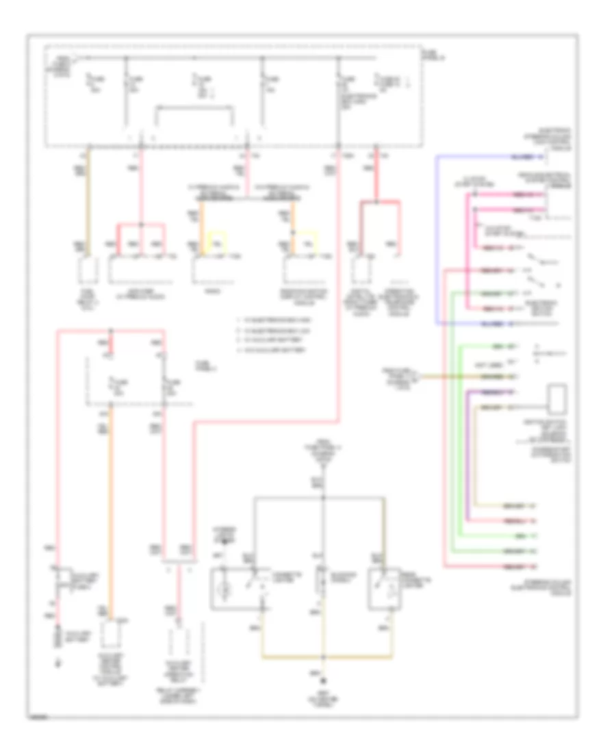
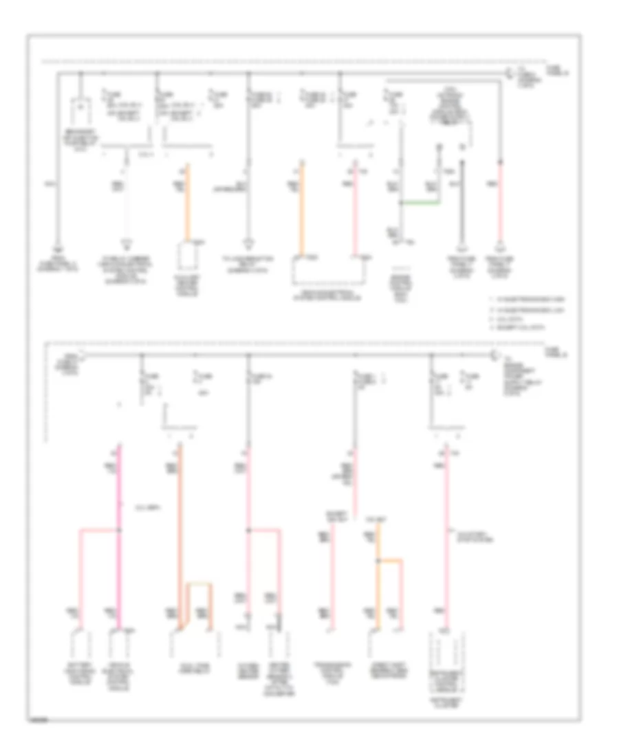
Power Distribution Wiring Diagram, Early Production (1 of 6) for Volkswagen CC VR6 4Motion 2010
 https://portal-diagnostov.com/license.html
Automotive Electricians Portal FZCO
Automotive Electricians Portal FZCO
https://portal-diagnostov.com/license.html
https://portal-diagnostov.com/license.html
Automotive Electricians Portal FZCO
Automotive Electricians Portal FZCO
List of elements for Power Distribution Wiring Diagram, Early Production (1 of 6) for Volkswagen CC VR6 4Motion 2010:
- 12a
- 13a
- 14a
- 15a
- 16a
- 17a
- 2.0l
- 22a
- 24a
- 26a
- 27a
- 28a
- 3.6l
- Abs control module
- Abs hydraulic unit
- Alarm horn relay
- Battery
- Comfort system central control module
- Coolant fan control (fc) module
- Data link connector (dlc)
- Driver's door control module
- Electro- mechanical parking brake button
- Electro- mechanical parking brake control module
- Electronic damping control module
- Electronic steering column lock control module
- From fuse panel f (diagram 2 of 6)
- Front passenger's door control module
- Fuel pump (fp) control module
- Fuse 10a
- Fuse 150a
- Fuse 15a
- Fuse 20a
- Fuse 40a
- Fuse 50a
- Fuse 5a
- Fuse 60a
- Fuse 80a
- Fuse panel a
- Fuse panel c
- Generator (except 2.0l ccta) generator (w/ voltage regulator) (2.0l ccta)
- Left rear door control module
- Light switch
- Nca
- Power steering control module
- Red
- Relay carrier (vehicle electrical system control module) (behind left side of dash)
- Relay carrier 2 (under left side of dash)
- Right rear door control module
- Starter
- T10s
- T18a
- T20g
- T20h
- T28
- T28a
- T28b
- T28c
- T2fn
- Terminal 30 wire junction
- Tiptronic switch (2.0l)
- To driver's power seat adjustment circuit breaker 1 (diagram 2 of 6)
- To electronic ignition switch (diagram 6 of 6)
- To fuse panel b (diagram 4 of 6)
- To fuse panel c (diagram 2 of 6)
- To fuse panel f (diagram 2 of 6)
- Vehicle electrical system control module
- W/ electronics box high
- W/ electronics box low
- Wire junction
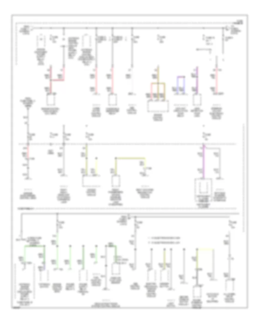
Power Distribution Wiring Diagram, Early Production (2 of 6) for Volkswagen CC VR6 4Motion 2010
List of elements for Power Distribution Wiring Diagram, Early Production (2 of 6) for Volkswagen CC VR6 4Motion 2010:
- (w/ rear view camera) fuse
- 15a
- 20a
- 29a
- 30a
- 31a
- 32a
- 33a
- 34a
- 35a
- 36a
- 37a
- 44a
- A/c control module (manual a/c)
- Auxiliary engine coolant heating rf receiver (if equipped)
- Battery interrupt igniter
- Climatronic control module (automatic a/c)
- Compass magnetic field sensor
- Converter w/ socket, 12v, 230v/115v
- Driver's door control module
- Driver's power seat adjustment circuit breaker 1
- Driver's seat adjustment control module
- Driver's seat adjustment switch
- Driver's seat lumbar support adjustment switch
- Electric socket control lamp
- From battery (diagram 1 of 6)
- From fuse panel a (diagram 1 of 6)
- From fuse panel c (diagram 1 of 6)
- Front heated seats control module
- Front passenger's door control module
- Front passenger's seat adjustment switch
- Front passenger's seat lumbar support adjustment switch
- Fuse 10a
- Fuse 125a
- Fuse 15a
- Fuse 20a
- Fuse 25a
- Fuse 30a
- Fuse 5a
- Fuse 60a
- Fuse 80a
- Fuse panel c
- Fuse panel f (3.6l)
- G687 (on center tunnel)
- Generator
- Headlamp washer relay
- Heated rear seats control module (if equipped)
- Left rear door control module
- Rain/light recognition sensor
- Rear lid handle release button
- Rear view camera system control module
- Rear window defogger relay
- Red
- Relay carrier (vehicle electrical system control module) (behind left side of dash)
- Relay carrier 1 (under left side of dash)
- Right rear door control module
- Sunroof control module
- T10c
- T10d
- T10s
- T12ab
- T20b
- T20c
- T20g
- T20h
- T28
- T28a
- T28b
- T28c
- T2dp
- T2ks
- T4a
- T6dc
- T6dd
- T8t
- To fuse panel b (diagram 4 of 6)
- To fuse panel c (diagram 1 of 6)
- To wire junction (diagram 1 of 6)
- Vehicle electrical system control module
- W/ memory
- W/o electronic height adjustment
- W/o memory
Power Distribution Wiring Diagram, Early Production (3 of 6) for Volkswagen CC VR6 4Motion 2010
List of elements for Power Distribution Wiring Diagram, Early Production (3 of 6) for Volkswagen CC VR6 4Motion 2010:
- (3.6l) (2.0l)
- 12v socket
- 2.0l
- 2.0l ccta
- 21a
- 38a
- 39a
- 41a
- 42a
- A/c control module (manual a/c)
- Automatic day/night interior mirror
- Backup light switch
- Brake light switch
- Data link connector (dlc)
- Direct shift gearbox (dsg) mechatronic (2.0l)
- Electronic damping control module
- Except 2.0l ccta
- Fresh air blower control module (automatic a/c)
- Fresh air blower relay (manual a/c w/ additional water heater)
- Fresh air blower relay (manual a/c)
- From fuse panel b (diagram 4 of 6)
- Fuse 10a
- Fuse 15a
- Fuse 20a
- Fuse 40a
- Fuse 5a
- Fuse 5a 20a
- Fuse panel c
- G51 (right side of luggage compt)
- G639 (on left "a" pillar)
- Headlamp range/ cornering lamp control module
- High pressure sensor
- Left headlamp assembly (w/ high intensity gas discharge headlights)
- Left rear heated seat regulating switch (if equipped)
- Left washer nozzle heater
- Light switch
- Load reduction relay
- Multi- function transmission range (tr) switch
- Nca
- Oil level thermal sensor (except 2.0l ccta)
- Power steering control module
- Relay carrier (vehicle electrical system control module) (behind left side of dash)
- Relay carrier 1 (under left side of dash)
- Right rear heated seat regulating switch (if equipped)
- Right washer nozzle heater
- Seat ventilation switch 1
- Seat ventilation switch 2
- T10c
- T10d
- T10f
- T20
- T2cp
- T2cq
- T3dt
- T52b
- T5r
- T68e
- T6ap
- T6e
- T9a
- To blocking diode 2 (diagram 6 of 6)
- To fuse 2 (diagram 5 of 6)
- To fuse panel c (diagram 5 of 6)
- Transmission control module (tcm)
- Vehicle electrical system control module
- W/ auxiliary heater
- W/o auxiliary heater
- Windshield washer pump
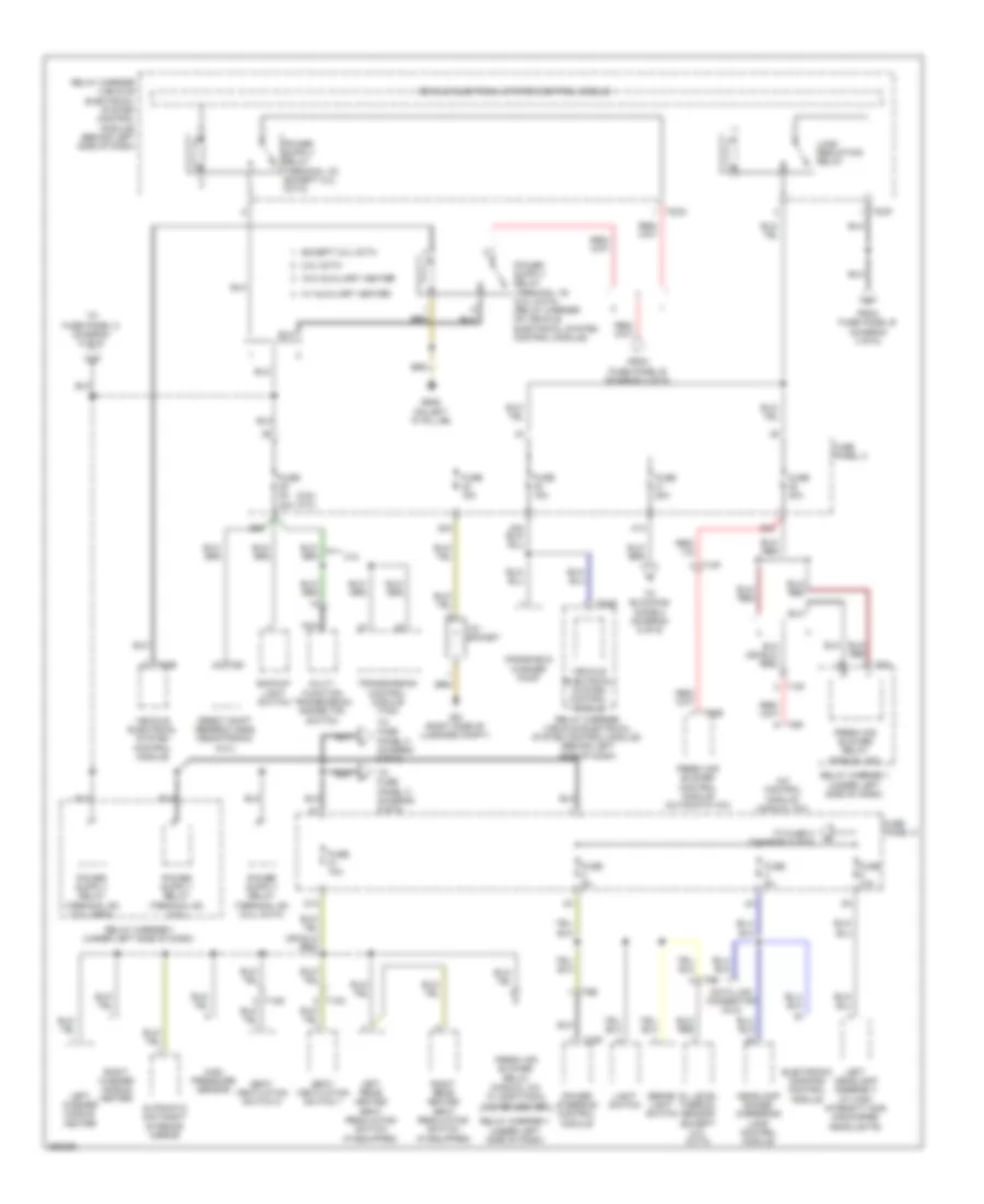
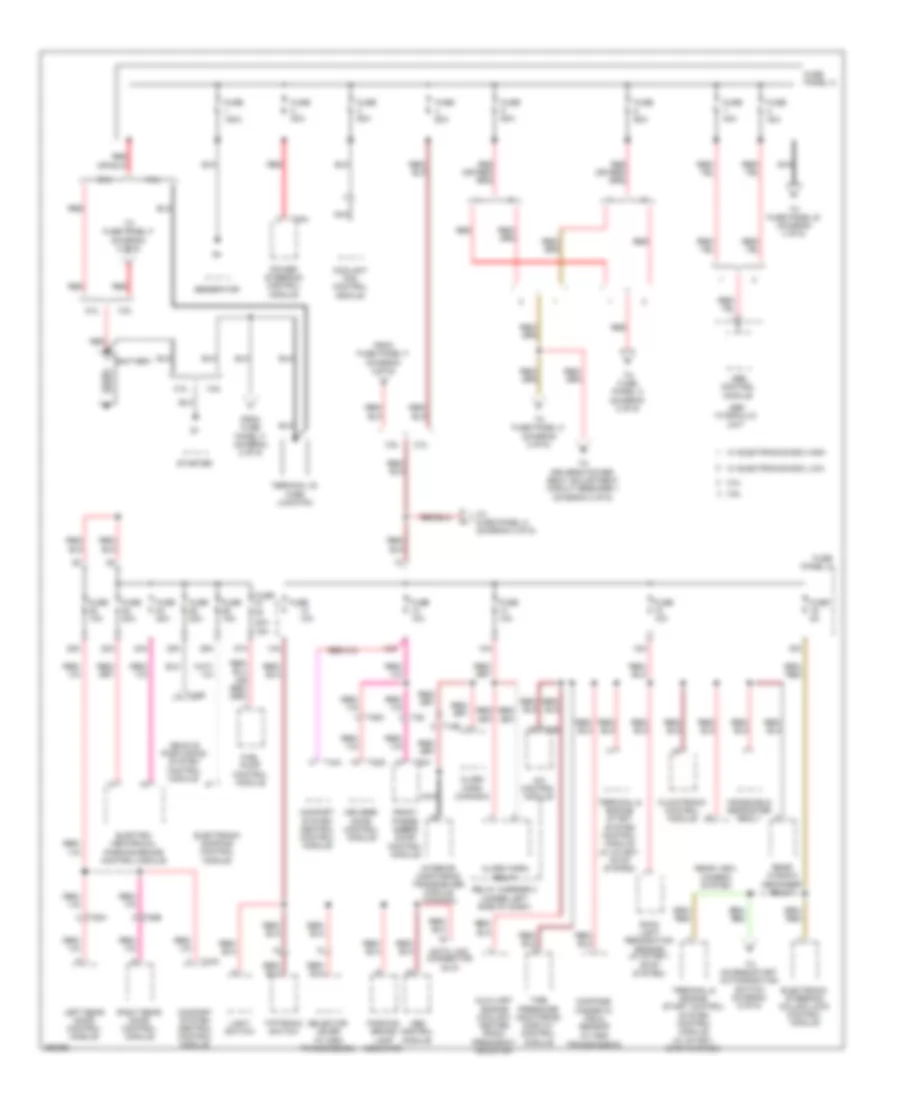
Power Distribution Wiring Diagram, Early Production (4 of 6) for Volkswagen CC VR6 4Motion 2010
List of elements for Power Distribution Wiring Diagram, Early Production (4 of 6) for Volkswagen CC VR6 4Motion 2010:
- (2.0l cbfa)
- (2.0l ccta)
- (2.0l) (3.6l)
- 2.0l
- 2.0l ccta
- 20a
- 3.6l
- 40a
- 50a
- Auxiliary heater control module
- Battery monitoring control module
- Data bus on board diagnostic interface
- Direct shift gearbox (dsg) mechatronic
- Dual horn relay
- Engine control module (ecm) (3.6l)
- Except 2.0l ccta
- From fuse panel a (diagram 1 of 6)
- From fuse panel f (diagram 2 of 6)
- From n fuse 47 (diagram 4 of 6)
- Fuse
- Fuse (3.6l) 50a
- Fuse 1 fuse 6 5a 15a
- Fuse 10a 40a
- Fuse 20a
- Fuse 20a 5a
- Fuse 24 fuse 15 5a
- Fuse 40a
- Fuse 48 fuse 25 40a
- Fuse 53 fuse 29 50a
- Fuse 5a
- Fuse panel b
- Instrument cluster
- Instrument cluster control module
- Nca
- Red
- Relay carrier (vehicle electrical system control module) (behind left side of dash)
- Secondary air injection pump relay (2.0l)
- T10s
- T11
- T11a
- T26a
- T2cn
- T40
- T52a
- T6ap
- T94
- To fuse 5 (diagram 4 of 6)
- To relay carrier (vehicle electrical system control module) (diagram 3 of 6)
- Transmission control module (tcm)
- Vehicle electrical system control module
- W/ electronics box high
- W/ electronics box low
- W/o start/ stop function
- W/o start/ stop system
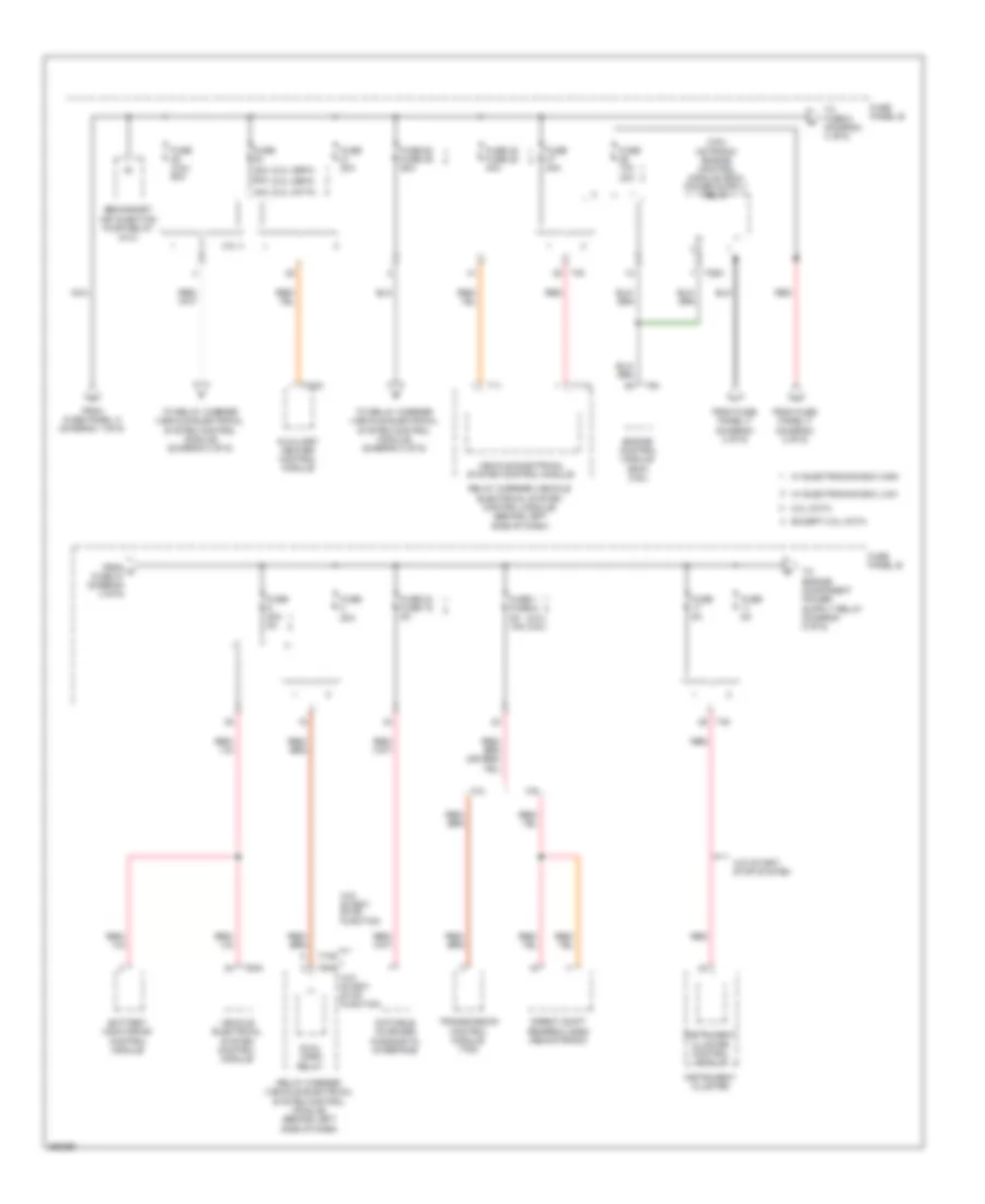
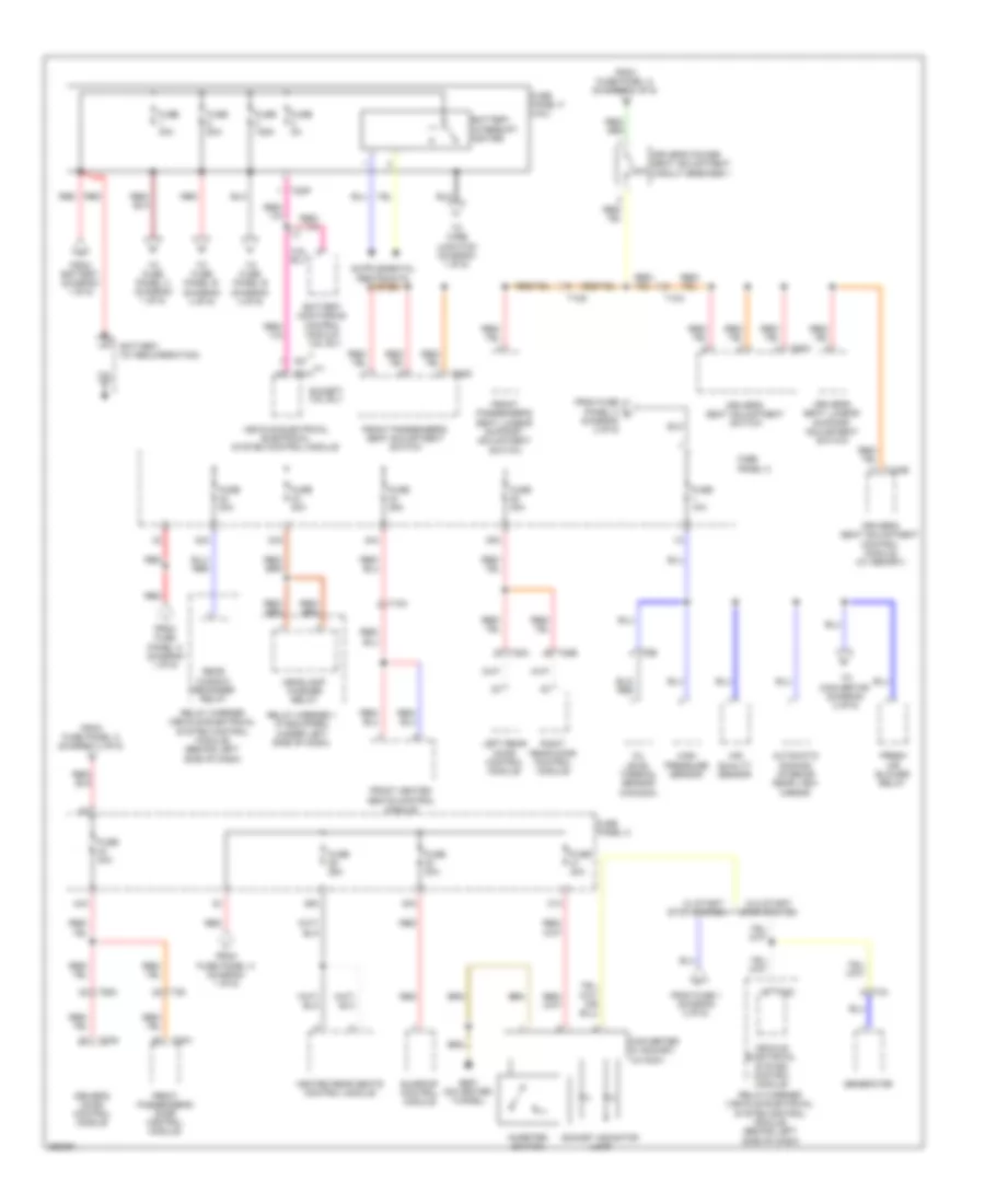
Power Distribution Wiring Diagram, Early Production (5 of 6) for Volkswagen CC VR6 4Motion 2010
List of elements for Power Distribution Wiring Diagram, Early Production (5 of 6) for Volkswagen CC VR6 4Motion 2010:
- (not used)
- 10a
- 19a
- 2.0l
- 2.0l ccta
- 20a
- 3.6l
- Abs control module
- Abs hydraulic unit
- Air bag control module
- All-wheel drive control module
- Asr/esp button
- Auto hold button (if equipped)
- Coolant circulation pump relay
- Data bus on board diagnostic interface
- Directional stabilization assistance control module
- Distance regulation control module
- Electro- mechanical parking brake control module
- Engine control module (ecm)
- Engine control module (ecm) (2.0l)
- From fuse panel c (diagram 3 of 6)
- From fuse panel c s (diagram 3 of 6)
- From o fuse 11 (diagram 4 of 6)
- From r fuse 5 (diagram 3 of 6)
- Front passenger's air bag disabled indicator lamp (if equipped)
- Fuel pump (fp) control module
- Fuse
- Fuse (2.0l w/ electronics box low) 10a
- Fuse 10a
- Fuse 16
- Fuse 30a
- Fuse 31 fuse 22 30a
- Fuse 52 fuse 27 60a
- Fuse 5a
- Fuse 7.5a
- Fuse 9 5a
- Fuse panel b
- Fuse panel c
- Garage door opener control head
- Heated oxygen sensor 2 after catalytic converter
- Instrument cluster
- Instrument cluster module
- Leak detection pump
- Mass air flow (maf) sensor
- Nca
- Oil level thermal sensor (2.0l ccta)
- Parallel parking assistance control module (w/ parallel parking)
- Parking aid control module (w/o parallel parking)
- Rear window shade control module
- Rear window shade switch
- Right headlamp assembly (w/ high intensity gas discharge headlights)
- Seat occupied recognition control module (w/ 16 ignition circuit)
- Steering column electronic systems control module
- T10a
- T10b
- T10e
- T16
- T16a
- T20d
- T26a
- T40
- T6e
- T8z
- T94
- Tiptronic switch (2.0l)
- To fuse 8 (diagram 6 of 6)
- W/ electronics box high
- W/ electronics box low
- Windshield heater relay
- Wiper motor control module
Power Distribution Wiring Diagram, Early Production (6 of 6) for Volkswagen CC VR6 4Motion 2010
List of elements for Power Distribution Wiring Diagram, Early Production (6 of 6) for Volkswagen CC VR6 4Motion 2010:
- (not used)
- 43a
- 45a
- 60a
- Access/start authorization switch
- Amplifier (w/ premium audio)
- Auxiliary battery
- Auxiliary battery fuse 2
- Auxiliary heater control module (w/ auxiliary battery)
- Auxiliary heater operation relay
- Blocking diode 2
- Cigarette lighter
- Digital satellite radio tuner (w/ premium audio)
- Electronic ignition switch
- Electronic steering column lock control module
- From fuse panel c (diagram 3 of 6)
- From fuse panel c v (diagram 1 of 6)
- From t fuse 9 (diagram 5 of 6)
- Fuel pump relay 2 (2.0l)
- Fuse (w/ electronics box high) 20a
- Fuse 15a
- Fuse 15a 30a
- Fuse 20 fuse 12 5a
- Fuse 20a
- Fuse 30a
- Fuse panel b
- Fuse panel c
- G687 (on center tunnel)
- Ignition switch key lock solenoid (w/ tiptronic)
- Interior lights system
- Operating electronics & telephone control module
- Radio
- Radio/navigation display control module
- Rear cigarette lighter
- Red
- Relay carrier 1 (under left side of dash)
- Steering column electronics control module
- T12m
- T16c
- T23
- T26a
- T2cn
- T40
- T8m
- Vehicle electrical system control module
- W/ auxiliary battery
- W/ electronics box high
- W/ electronics box low
- W/ premium audio & external audio source
- W/ stop/ start system
- W/o auxiliary battery
- W/o premium audio & external audio source
- W/o stop/ start system
Power Distribution Wiring Diagram, Late Production (1 of 6) for Volkswagen CC VR6 4Motion 2010
List of elements for Power Distribution Wiring Diagram, Late Production (1 of 6) for Volkswagen CC VR6 4Motion 2010:
- (w/ dsg transmission)
- 10a
- 12a
- 13a
- 14a
- 15a
- 16a
- 2.0l
- 20a
- 22a
- 24a
- 25a
- 26a
- 27a
- 28a
- 3.6l
- A/c control module
- Abs control module
- Abs hydraulic unit
- Alarm horn (canada)
- Alarm horn relay
- Auxiliary engine coolant heater radio frequency receiver
- Battery
- Climatronic control module
- Comfort system central control module
- Compass magnetic field sensor
- Coolant fan control module
- Data link connector (dlc)
- Driver's door control module
- Electro- mechanical parking brake control module
- Electronic damping control module
- Electronic steering column lock control module
- From fuse panel f (diagram 2 of 6)
- Front passe- nger's door control module
- Fuel pump control module
- Fuse
- Fuse 10a
- Fuse 150a
- Fuse 15a
- Fuse 20a
- Fuse 40a
- Fuse 50a
- Fuse 5a
- Fuse 60a
- Fuse 80a
- Fuse panel a
- Fuse panel c
- Generator
- Interior monitoring transceiver module (canada)
- Left rear door control module
- Light switch
- Nca
- Parking brake lamp indicator
- Power steering control module
- Rain/ light recognition sensor (w/ start/ stop system)
- Rear view camera system
- Rear window defogger relay
- Red
- Relay carrier 2 (under left side of dash)
- Right rear door control module
- Selector lever (w/ dsg transmission)
- Starter
- T10e
- T16r
- T18a
- T20b
- T20g
- T20h
- T28
- T28a
- T28b
- T28c
- T2fn
- Terminal & engine start control system control module (w/ start/ stop system)
- Terminal & engine start system control module (w/ start/ stop system)
- Terminal 30 wire junction
- Tiptronic switch
- Tire pressure monitoring display control module
- To access/start authorization switch (diagram 6 of 6)
- To driver's power seat adjustment circuit breaker 1 (diagram 2 of 6)
- To fuse panel b (diagram 4 of 6)
- To fuse panel c (diagram 2 of 6)
- To fuse panel f (diagram 2 of 6)
- Vehicle positioning system control module
- W/ electronics box high
- W/ electronics box low
- Windshield defroster realy
Power Distribution Wiring Diagram, Late Production (2 of 6) for Volkswagen CC VR6 4Motion 2010
List of elements for Power Distribution Wiring Diagram, Late Production (2 of 6) for Volkswagen CC VR6 4Motion 2010:
- 20a
- 29a
- 3.6l blv
- 30a
- 31a
- 32a
- 33a
- 34a
- 35a
- 44a
- Air quality sensor
- Automatic dimming interior rear view mirror
- Battery (w/ recuperation)
- Battery interrupt igniter
- Battery monitoring control module
- Converter w/ socket, 12v/230v
- Driver's door control module
- Driver's power seat adjustment circuit breaker 1
- Driver's seat adjustment control module (w/ memory)
- Driver's seat adjustment switch
- Driver's seat lumbar support adjustment switch
- Except 3.6l blv
- Fresh air blower relay
- From battery (diagram 1 of 6)
- From fuse 1 (diagram 2 of 6)
- From fuse panel a (diagram 1 of 6)
- From fuse panel c (diagram 1 of 6)
- From fuse panel c o (diagram 3 of 6)
- Front heated seats control module
- Front passenger's door control module
- Front passenger's seat adjustment switch
- Front passenger's seat lumbar support adjustment switch
- Fuse 10a
- Fuse 125a
- Fuse 25a
- Fuse 30a
- Fuse 5a
- Fuse 80a
- Fuse panel c
- Fuse panel f (3.6l)
- G687 (on center tunnel)
- Generator
- Headlamp washer relay
- Heated rear seats control module
- High pressure sensor
- Inverter switch
- Left rear door control module
- Oil level thermal sensor (canada)
- Rear window defogger relay
- Red
- Relay carrier (vehicle electrical system control module) (behind left side of dash)
- Relay carrier 1 (if equipped) (under left side of dash)
- Right rear door control module
- Socket indicator lamp
- Sunroof control module
- T10c
- T10d
- T12ab
- T20g
- T20h
- T28
- T28a
- T28b
- T28c
- T2dp
- T4a
- T52a
- T52c
- T6dc
- T6dd
- T6e
- T8t
- To convertor (diagram 2 of 6)
- To fuse panel b (diagram 4 of 6)
- To fuse panel c (diagram 1 of 6)
- To wire junction (diagram 1 of 6)
- Vehicle electrical electrical system control module
- Vehicle electrical system control module
- W/ start/ stop system
- W/o start/ stop system
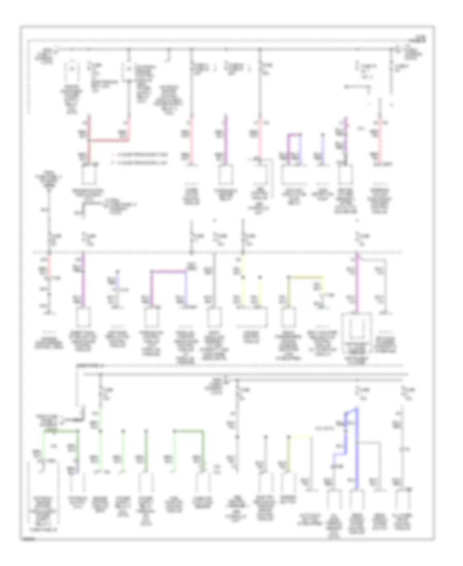
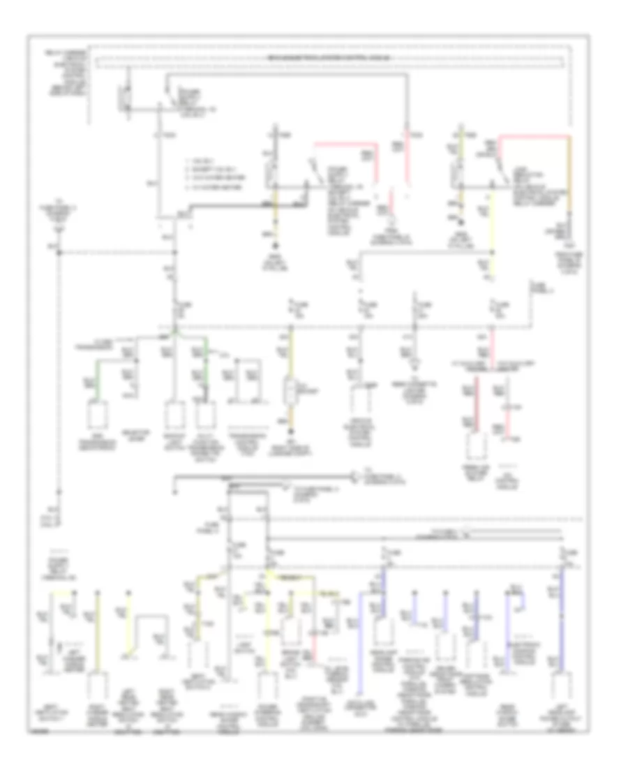
Power Distribution Wiring Diagram, Late Production (3 of 6) for Volkswagen CC VR6 4Motion 2010
List of elements for Power Distribution Wiring Diagram, Late Production (3 of 6) for Volkswagen CC VR6 4Motion 2010:
- (2.0l)
- (3.6l)
- 12v socket
- 2.0l
- 21a
- 3.6l blv
- 38a
- 39a
- 40a
- 41a
- 42a
- A/c control module
- Backup light switch
- Brake light switch (3.6l blv)
- Data link connector (dlc)
- Distance regulation control module
- Driver assistance front camera system
- Dsg transmission mechatronic
- Electronic damping control module
- Except 3.6l blv
- Fresh air blower relay
- From fuse panel b (diagram 4 of 6)
- Fuse 10a
- Fuse 15a
- Fuse 20a
- Fuse 40a
- Fuse 5a
- Fuse panel c
- G51 (right side of luggage compt)
- G639 (on left "a" pillar)
- Headlamp range control module
- Left headlamp power output stage (w/ xenon)
- Left rear heated seat regulating switch (if equipped)
- Left washer nozzle heater
- Light switch
- Load reduction relay (on vehicle electrical system control module relay carrier)
- Multi- function transmission range (tr) switch
- Nca
- Oil level thermal sensor (3.6l blv)
- Parking aid control module (w/o parallel parking assistance) parallel parking assistance control module (w/ parallel parking assistance)
- Positive crankshaft ventilation healing element (3.6l cnna)
- Power steering control module
- Rear window shade control module
- Rear window shade switch
- Relay carrier (vehicle electrical system control module) (behind left side of dash)
- Right rear heated seat regulating switch (if equipped)
- Right washer nozzle heater
- Seat ventilation switch 1
- Seat ventilation switch 2
- Selector lever
- T10a
- T10c
- T10d
- T10f
- T14e
- T16
- T2cq
- T52b
- T5r
- T6e
- To fuse 2 (diagram 5 of 6)
- To fuse panel c (diagram 2 of 6)
- To fuse panel c (diagram 5 of 6)
- To rear cigarette lighter (diagram 6 of 6)
- Transmission control module (tcm)
- Vehicle electrical system control module
- W/ auxiliary heater
- W/ dsg transmission
- W/ water heater
- W/o auxiliary heater
- W/o water heater
Power Distribution Wiring Diagram, Late Production (4 of 6) for Volkswagen CC VR6 4Motion 2010
List of elements for Power Distribution Wiring Diagram, Late Production (4 of 6) for Volkswagen CC VR6 4Motion 2010:
- (3.6l blv)
- (except 3.6l blv)
- 2.0l cbfa
- 2.0l ccta
- 20a
- 3.6l blf
- 40a
- Auxiliary heater control module
- Battery monitoring control module
- Direct shift gearbox (dsg) mechatronic
- Dual tone horn relay
- Engine control module (ecm) (3.6l)
- Except 2.0l ccta
- Except 3.6l blf
- From fuse panel a (diagram 1 of 6)
- From fuse panel f (diagram 2 of 6)
- From u fuse 47 (diagram 4 of 6)
- Fuse
- Fuse 1 fuse 6 5a
- Fuse 10a 40a
- Fuse 20a
- Fuse 20a 5a
- Fuse 24 15a
- Fuse 40a
- Fuse 48 fuse 25 40a
- Fuse 50a
- Fuse 53 fuse 29 50a
- Fuse 5a
- Fuse 5a 40a
- Fuse panel b
- Heated oxygen sensor 2 after catalytic converter
- Instrument cluster
- Instrument cluster control module
- Nca
- Oxygen heater sensor
- Red
- Secondary air injection pump relay (2.0l)
- T26a
- T2cn
- T40
- T52a
- T52c
- T94
- To fuse 5 (diagram 4 of 6)
- To load reduction relay (diagram 3 of 6)
- To relay carrier (vehicle electrical system control module) (diagram 3 of 6)
- Transmission control module (tcm)
- Vehicle electrical system control module
- W/ electronics box high
- W/ electronics box low
- W/o start/ stop system
Power Distribution Wiring Diagram, Late Production (5 of 6) for Volkswagen CC VR6 4Motion 2010
List of elements for Power Distribution Wiring Diagram, Late Production (5 of 6) for Volkswagen CC VR6 4Motion 2010:
- (2.0l)
- (3.6l blv)
- (3.6l cnna)
- (not used)
- 10a
- 20a
- Abs control module
- Air bag control module
- All-wheel drive control module
- Asr/esp button
- Auto hold button (if equipped)
- Center console switch module 1
- Coolant circulation pump relay
- Data bus on board diagnostic interface
- Electro- mechanical parking brake control module
- Engine control module
- Engine control module (ecm)
- Engine control module (ecm) (2.0l cbfa)
- From fuse 11 v (diagram 4 of 6)
- From fuse panel c (diagram 3 of 6)
- From r fuse 5 (diagram 3 of 6)
- Front passenger's air bag disabled indicator lamp (if equipped)
- Fuel pump (fp) control module
- Fuse
- Fuse 10a
- Fuse 16
- Fuse 25a
- Fuse 30a
- Fuse 31 fuse 22 30a
- Fuse 52 fuse 27 60a
- Fuse 5a
- Fuse 9 5a
- Fuse panel b
- Fuse panel b (3.6l blv)
- Fuse panel c
- Garage door opener control head
- Instrument cluster
- Instrument cluster module
- Leak detection pump (usa)
- Light switch
- Mass air flow (maf) sensor
- Nca
- Power steering control module
- Right front headlamp (w/ dynamic cornering lamp)
- Seat occupied recognition control module
- Steering column electronic control module
- T10b
- T10e
- T20d
- T26a
- T30t
- T40
- T6e
- T8z
- T94
- Tiptronic switch
- To fuse 8 (diagram 6 of 6)
- Vehicle positioning system control module
- W/ electronics box high
- W/ electronics box low
- Windshield defroster relay
- Wiper motor control module
Power Distribution Wiring Diagram, Late Production (6 of 6) for Volkswagen CC VR6 4Motion 2010
List of elements for Power Distribution Wiring Diagram, Late Production (6 of 6) for Volkswagen CC VR6 4Motion 2010:
- (if equipped)
- (if equipped) telephone electrical system control module
- (not used)
- 43a
- 45a
- 60a
- Access/start authorization switch
- Amplifier (w/ premium audio)
- Analog clock
- Auxiliary battery
- Auxiliary battery fuse 2
- Auxiliary heater control module (w/ auxiliary battery)
- Auxiliary heater operation relay
- Cellphone operating electronics control module
- Cigarette lighter
- Electronic ignition switch
- Electronic steering column lock control module
- Engine control module
- From fuse 9 (diagram 5 of 6)
- From fuse panel c (diagram 3 of 6)
- From fuse panel c g (diagram 1 of 6)
- Fuel pump relay 2
- Fuse 15a
- Fuse 15a 30a
- Fuse 20 fuse 12 5a
- Fuse 20a
- Fuse 27 fuse 52 60a
- Fuse 30a
- Fuse panel b
- Fuse panel c
- G687 (on center tunnel)
- Ignition switch key lock solenoid (w/ tiptronic)
- Interior lights system
- Operating electronics & telephone control module
- Radio
- Radio/navigation display control module
- Rear cigarette lighter
- Red
- Relay carrier 1 (w/ access/start authorization) (under left side of dash)
- Steering column electronics control module
- T16c
- T23
- T26a
- T2cn
- T40
- T52c
- T94
- Terminal & engine start control module
- Terminal & engine start control system control module
- Tv tuner
- Vehicle electrical system control module
- W/ access/start authorization
- W/ auxiliary battery
- W/ electronics box high
- W/ electronics box low
- W/ navigation
- W/o access/start authorization
- W/o auxiliary battery
- W/o navigation
- Windshield defogger relay

 Čeština
 Dansk
Dansk Deutsch
 Ελληνικά
 English
 Español
 Suomi
Suomi Français
 Français
 עברית
עברית Hrvatski
 Magyar
 Italiano
 日本語
日本語 한국어
한국어 Nederlands
 Polski
 Português
 Português
 Română
 Русский
 Slovenčina
 Slovenščina
 Svenska
 Türkçe
 中文 (中国)