POWER DISTRIBUTION
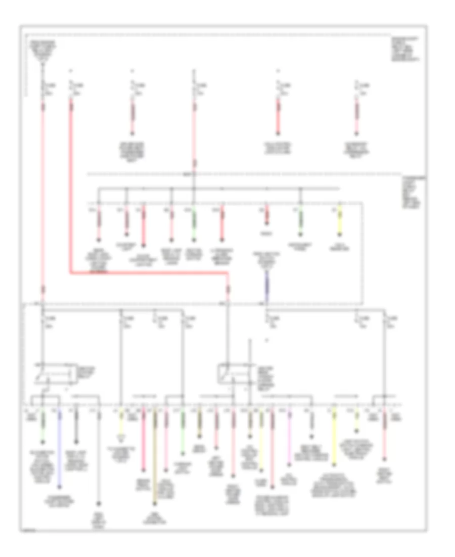
Power Distribution Wiring Diagram (1 of 3) for Volvo S40 2000
 https://portal-diagnostov.com/license.html
Automotive Electricians Portal FZCO
Automotive Electricians Portal FZCO
https://portal-diagnostov.com/license.html
https://portal-diagnostov.com/license.html
Automotive Electricians Portal FZCO
Automotive Electricians Portal FZCO
List of elements for Power Distribution Wiring Diagram (1 of 3) for Volvo S40 2000:
- Abs control module
- Accessory relay (in passenger compartment fuse & relay box)
- Alarm horn
- Battery
- Brake pedal switch for locking gear shift selector
- Central electronic module (cem)
- Cigarette lighter
- Engine compartment fuse & relay box (on left rear corner of engine compt)
- Engine cooling fan, a/c condenser fan
- From passenger compt fuse & relay box (diagram 2 of 3)
- From passenger compt fuse & relay box (diagram 3 of 3)
- Fuel pump
- Fuel system relay
- Fuse 10a
- Fuse 120a
- Fuse 15a
- Fuse 20a
- Fuse 30a
- Fuse 40a
- Fuse 50a
- G111 (near battery)
- G202 (left side of dash)
- Generator
- Immobilizer control module, fuel system relay, engine control module, automatic transmission control module (tcu)
- Pnk
- Power windows
- Pressure switch vacuum pump ems 2000 turbo
- Red
- Starter
- To engine compt fuse & relay box (diagram 2 of 3)
- To ignition switch (diagram 3 of 3)
- Vacuum pump ems 2000 turbo
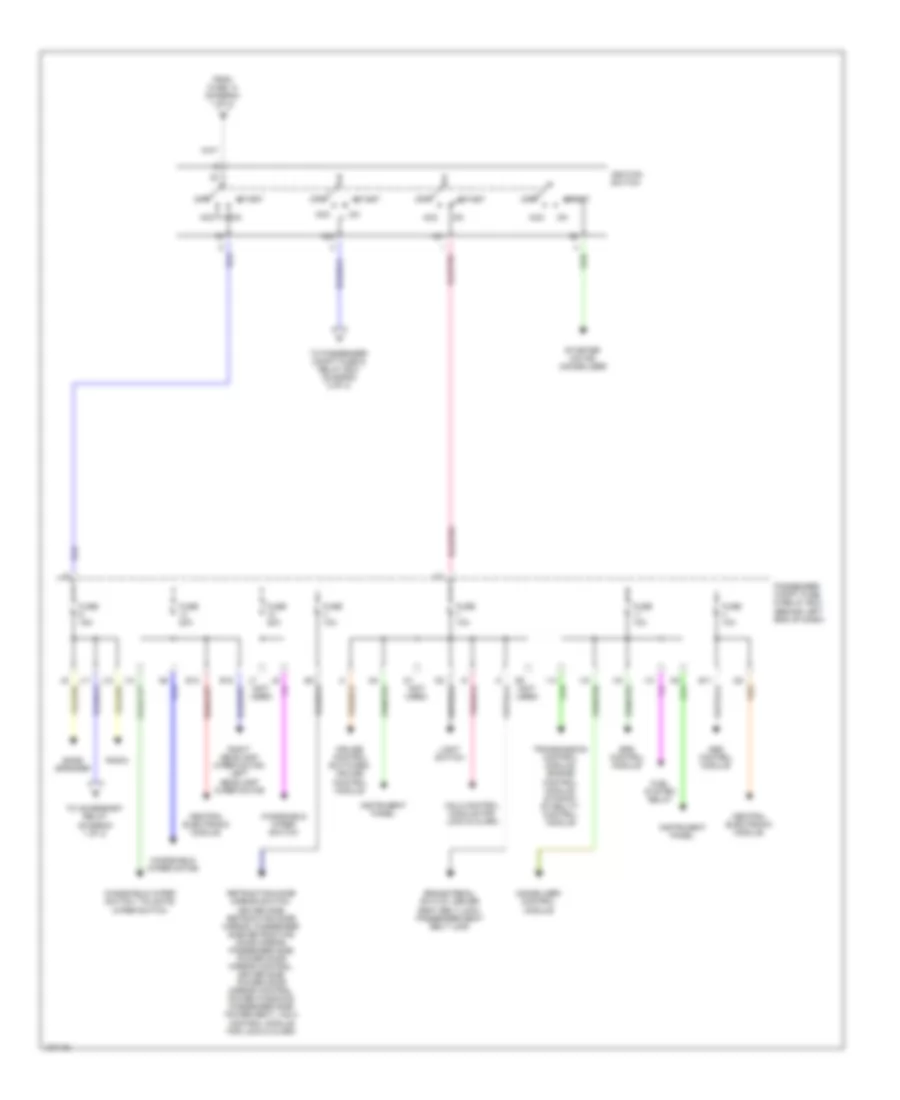
Power Distribution Wiring Diagram (2 of 3) for Volvo S40 2000
List of elements for Power Distribution Wiring Diagram (2 of 3) for Volvo S40 2000:
- (not used)
- A/c control module
- A/c control module, ecc control module
- Accessory relay, a/c compressor relay
- Alarm horn
- Automatic transmission, auto trans switch (econo/sport), auto trans switch (winter), back-up lamp switch
- Blower fan motor switch, max speed blower fan motor, ecc control module
- Brake pedal switch
- C12
- C17
- Courtesy light
- Driver side power seat, passenger side power seat
- E10
- Engine compt fuse & relay box (left rear corner of engine compt)
- From engine compt fuse & relay box (diagram 1 of 3)
- From ignition switch (diagram 3 of 3)
- Fuse 10a
- Fuse 15a
- Fuse 20a
- Fuse 25a
- Fuse 30a
- Fuse 50a
- G11
- G12
- G13
- G14
- G15
- G16
- G202 (left side of dash)
- Glove compartment lighting
- Heated rear window & door mirrors relay
- Heating system relay
- I18
- Ignition warning switch
- Instrument panel
- J14
- J15
- J16
- J18
- Left heated power door mirror
- Light switch, switch warning light, central electronic module
- Obd system connector
- Passenger compt blower motor fan
- Passenger compt fuse & relay box (behind left end of dash)
- Pnk
- Power sunroof control module, roof lamp for ll, roof lamp for hl w/ reading lamp
- Radio
- Rear demist
- Rear roof lamp, cargo compt lighting, power antenna
- Red
- Right heated power door mirror
- Right heated seat switch
- Roof lamp for hl w/ reading lamps
- Roof lamp for hl w/ reading lamps, roof lamp for ll
- Seat belt reminder, ignition warning control module
- To cigarette lighter (diagram 1 of 3)
- Ultrasonic glass breakage sensor
- Vgla control module for lock & alarm
- Vgla receiver
- Warning light switch
Power Distribution Wiring Diagram (3 of 3) for Volvo S40 2000
List of elements for Power Distribution Wiring Diagram (3 of 3) for Volvo S40 2000:
- (not used)
- 15/1
- 15/2
- Abs control module
- Acc
- Bass speaker
- Brake pedal switch, driver seat belt lock, passenger seat belt lock
- Central electronic module
- Cruise control switches, cruise control module
- E11
- E13
- E15
- From fuse 14 (diagram 1 of 3)
- Fuel system relay
- Fuse 10a
- Fuse 15a
- Fuse 20a
- I12
- I13
- I14
- I15
- I16
- I22
- Ignition switch
- Immobilizer control module
- Instrument panel
- J10
- J11
- J12
- Light switch
- Off
- Passenger compt fuse & relay box (behind left end of dash)
- Radio
- Retracting door mirror switch, driver side retracting door mirror, passenger side retracting door mirror, passenger side power door mirror control, driver side power door mirror control, power windows, passenger side power seat, vgla control module for lock & alarm
- Right headlamp wiper motor, left headlamp wiper motor
- Srs control module
- Start
- Starter motor (immobilizer)
- To accessory relay (diagram 1 of 3)
- To passenger compt fuse & relay box (diagram 2 of 3)
- Transmission control module, engine control module, dynamic stability control module
- Vgla control module for lock & alarm
- Windshield wiper motor
- Windshield wiper switch
- Windshield wiper switch, tailgate wiper switch

 Čeština
 Dansk
Dansk Deutsch
 Ελληνικά
 English
 Español
 Suomi
Suomi Français
 Français
 עברית
עברית Hrvatski
 Magyar
 Italiano
 日本語
日本語 한국어
한국어 Nederlands
 Polski
 Português
 Português
 Română
 Русский
 Slovenčina
 Slovenščina
 Svenska
 Türkçe
 中文 (中国)