POWER DISTRIBUTION
Power Distribution Wiring Diagram for Volvo V50 T-5 2005
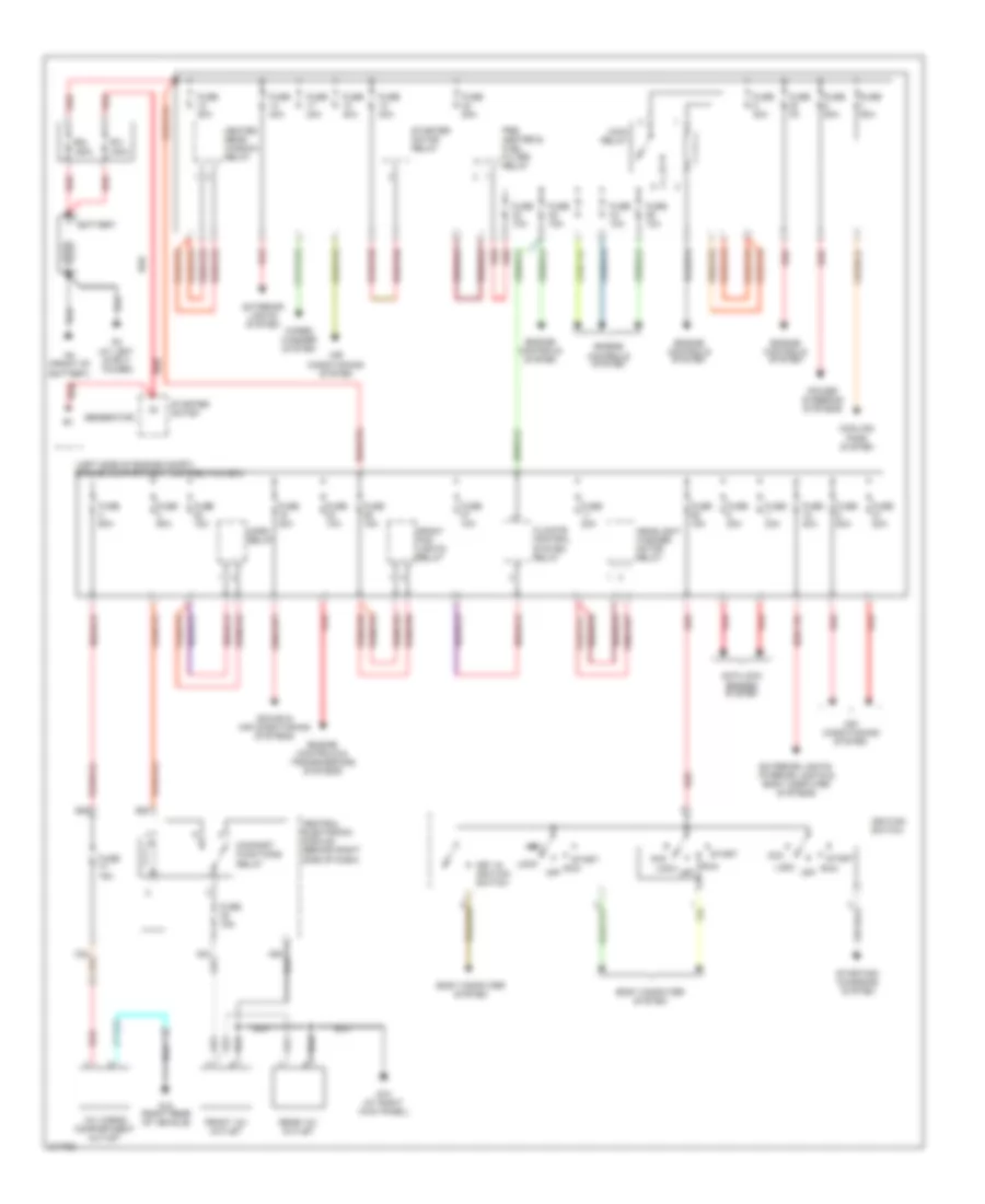
List of elements for Power Distribution Wiring Diagram for Volvo V50 T-5 2005:
- (left side of engine compt) engine compartment distribution box
- 12v cargo compartment outlet
- A23
- A28
- Acc
- Air conditioning system
- Anti-lock brakes system
- Battery
- Body computer system
- C22
- Central electronic module (behind right side of dash)
- Climate control system relay
- Comfort functions relay
- Cooling fans system
- E20
- E22
- Engine controls & transmissions systems
- Engine controls system
- Exterior lights system
- Exterior lights, interior lights & body computer systems
- Front 12v outlet
- Front fog lights relay
- Fuse 10a
- Fuse 15a
- Fuse 20a
- Fuse 30a
- Fuse 3a
- Fuse 40a
- Fuse 50a
- Fuse 60a
- Fuse 80a
- G10 (at right kick panel)
- G12 (right rear of vehicle)
- G3 (at left strut tower)
- G4 (front of battery)
- Generator
- Headlight washer motor relay
- Heated rear window relay
- Horn relay
- Ignition switch
- Key in ignition switch
- Lock
- Main relay
- Off
- Pf1 150a
- Pf2 150a
- Power steering systems
- Pre heater & fuel filter relay
- Rear 12v outlet
- Red
- Run
- Sound & air conditioning systems
- Start
- Starter motor
- Starter motor relay
- Starting/ charging system
- Wiper/ washer system
 Čeština
 Dansk
Dansk Deutsch
 Ελληνικά
 English
 English
 Español
 Suomi
Suomi Français
 Français
 עברית
עברית Hrvatski
 Magyar
 Italiano
 日本語
日本語 한국어
한국어 Polski
 Português
 Português
 Română
 Русский
 Slovenčina
 Slovenščina
 Svenska
 Türkçe
 中文 (中国)
 Nederlands