RADIO
Base Radio Wiring Diagram for Ford Mustang Shelby GT500 2012
 https://portal-diagnostov.com/license.html
Automotive Electricians Portal FZCO
Automotive Electricians Portal FZCO
https://portal-diagnostov.com/license.html
https://portal-diagnostov.com/license.html
Automotive Electricians Portal FZCO
Automotive Electricians Portal FZCO
List of elements for Base Radio Wiring Diagram for Ford Mustang Shelby GT500 2012:
- Ant
- Antenna
- Audio control module (acm) (lower center of dash)
- Audio input jack (w/o sync)
- C210
- C213
- C214
- C2280a
- C2280b
- C260
- C290a
- C290d
- Cbp28
- Cme44
- Coaxial cable
- Computer data lines system
- Dme35
- Dme45
- Drain
- Fuse 20a
- Fuse 5a
- G202 (center of dash)
- Gd115
- Hot at all times
- Hot in start
- Left door speaker
- Left quarter panel speaker
- Lf spkr +
- Lf spkr -
- Lr spkr +
- Lr spkr -
- Ms can +
- Ms can -
- Nca
- Rf spkr +
- Rf spkr -
- Right door speaker
- Right quarter panel speaker
- Rme07
- Rme09
- Rme10
- Rme12
- Rme45
- Rme46
- Rr spkr +
- Rr spkr -
- S210
- Sbp39
- Smart junction box (sjb) (right kick panel)
- St input 2l+
- St input 2l-
- St input 2r+
- St input 2r-
- Start
- Stereo 1 l+
- Stereo 1 l-
- Stereo 2 r+
- Stereo 2 r-
- System gnd
- Vdb06
- Vdb07
- Vme07
- Vme09
- Vme10
- Vme12
- Vme35
- Vme45
- Vme46
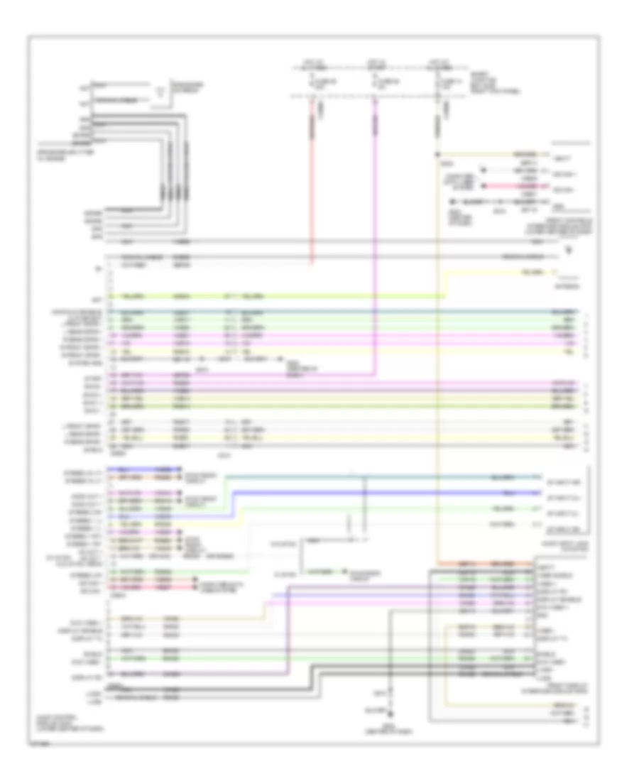
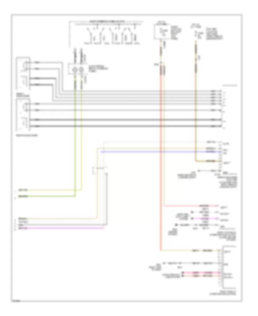
Premium Radio Wiring Diagram, with Navigation (1 of 4) for Ford Mustang Shelby GT500 2012
List of elements for Premium Radio Wiring Diagram, with Navigation (1 of 4) for Ford Mustang Shelby GT500 2012:
- (center of dash)
- (or dme45)
- (or nca)
- (w/ sync)
- (w/o sync)
- Ant
- Antenna
- Audio control module (acm) (lower center of dash)
- Audio input jack (w/o sync)
- C210
- C2280a
- C2280b
- C290a
- C290c
- C290d
- Cbp28
- Cme31
- Cme44
- Cmn23
- Cmn24
- Cmn26
- Coaxial cable
- Computer data lines system
- Display enable
- Display rx
- Display tx
- Dme17
- Dme35
- Dme41
- Dmn03
- Dmn20
- Dmp19
- Dvd video +
- Dvd video -
- Front controls interface module (fcm) (lower center of dash)
- Front display interface module (fdim)
- Fuse 14 10a
- Fuse 28 5a
- Fuse 39 20a
- G202
- G202 (center of dash)
- Gd115
- Gnd
- Gps
- Gps/sdars antenna
- Gps/sdars splitter (w/ sdars)
- Hot at all times
- Hot in start
- L front spkr -
- L rear spkr +
- L rear spkr -
- Lvds+
- Lvds-
- Main/aux3 enable/ clip detect l front spkr +
- Mc out +
- Mc out - drain
- Mono out +
- Ms can +
- Ms can -
- Nca
- Nca ant
- Nca gps
- Nca sdars
- R front spkr +
- R front spkr -
- R rear spkr +
- R rear spkr -
- Rme14
- Rme17
- Rme18
- Rme45
- Rme46
- Rme52
- Rme53
- Rme54
- Rme60
- Rme61
- Rmn14
- Rmn20
- Rmn25
- Rmp19
- S210
- S232
- Sbp14
- Sbp39
- Sdars
- Shield
- Smart junction box (sjb) (right kick panel)
- St input 2l+
- St input 2l-
- St input 2r+
- St input 2r-
- Start
- Stereo 1 l+
- Stereo 1 l-
- Stereo 1 rt+
- Stereo 1 rt-
- Stereo 2 r+
- Stereo 2 r-
- Stereo in lt+
- Stereo in lt-
- Swc1 +
- Swc1 -
- Swc2 +
- Swc2 -
- Sync radio circuit
- Sync radio circuit rmm23
- System gnd
- Vbatt
- Vdb06
- Vdb07
- Video +
- Video -
- Video shield
- Vme14
- Vme17
- Vme18
- Vme35
- Vme43
- Vme45
- Vme46
- Vme52
- Vme53
- Vme54
- Vme60
- Vme61
- Vmm23
- Vmn03
- Vmn14
- Vmn20
- Vmn25
- Vmp19
- W/ sync
- W/o sync
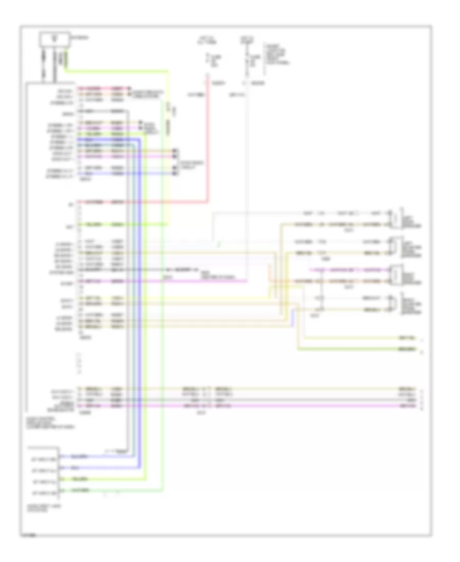
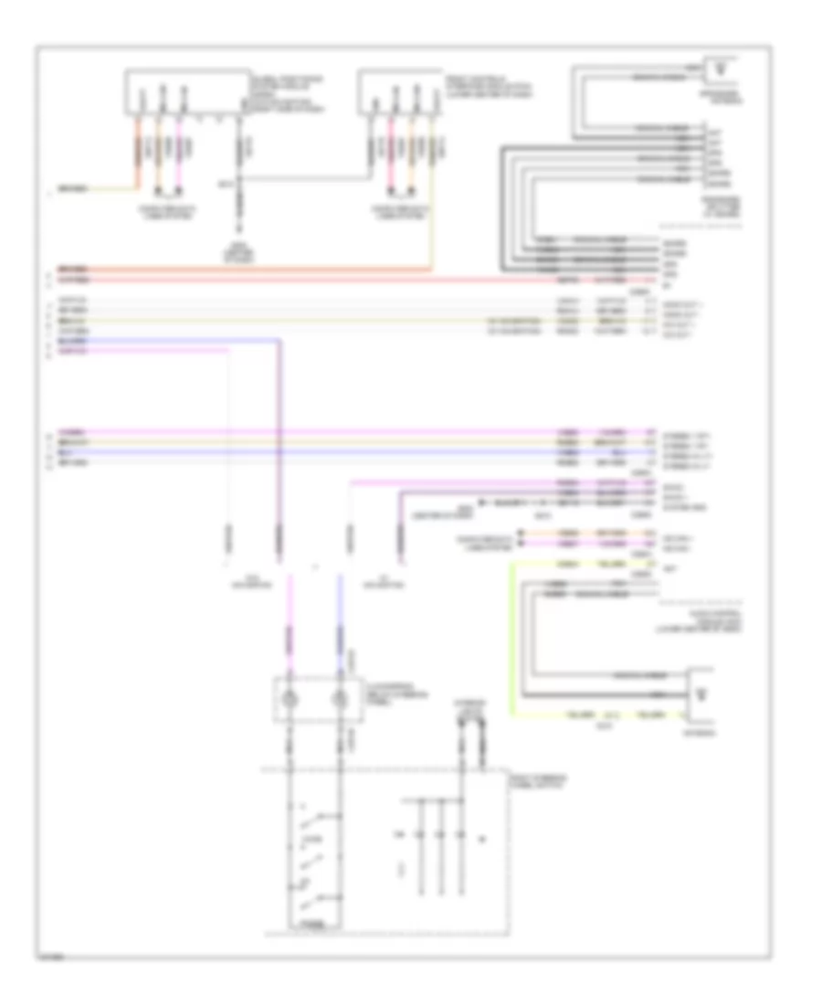
Premium Radio Wiring Diagram, with Navigation (2 of 4) for Ford Mustang Shelby GT500 2012
List of elements for Premium Radio Wiring Diagram, with Navigation (2 of 4) for Ford Mustang Shelby GT500 2012:
- (right side of dash)
- Audio amplifier (right rear of luggage compt)
- C210
- C213
- C214
- C2280b
- C2280d
- C260
- C4364a
- C4364b
- Cme31
- Fuse 19 25a
- Fuse 29 5a
- G201
- G401 (rear center of luggage compt)
- Gd173
- Gnd
- Ground
- Ground distribution system
- Hot at all times
- Hot in run or start
- Left door speaker
- Left quarter panel speaker
- Lf spkr+
- Lf spkr-
- Lr spkr+
- Lr spkr-
- Main/aux3 en- able/clip detect
- Nca
- Rear video camera (if equipped) (center of trunk lid)
- Rf spkr+
- Rf spkr-
- Right door speaker
- Right quarter panel speaker
- Rme07
- Rme09
- Rme10
- Rme12
- Rme17
- Rme18
- Rme60
- Rme61
- Rr spkr+
- Rr spkr-
- S201
- Sbp19
- Smart junction box (sjb) (right kick panel)
- Vbatt
- Video +
- Video -
- Video shield
- Vme07
- Vme09
- Vme10
- Vme12
- Vme17
- Vme18
- Vme60
- Vme61
- Vpwr
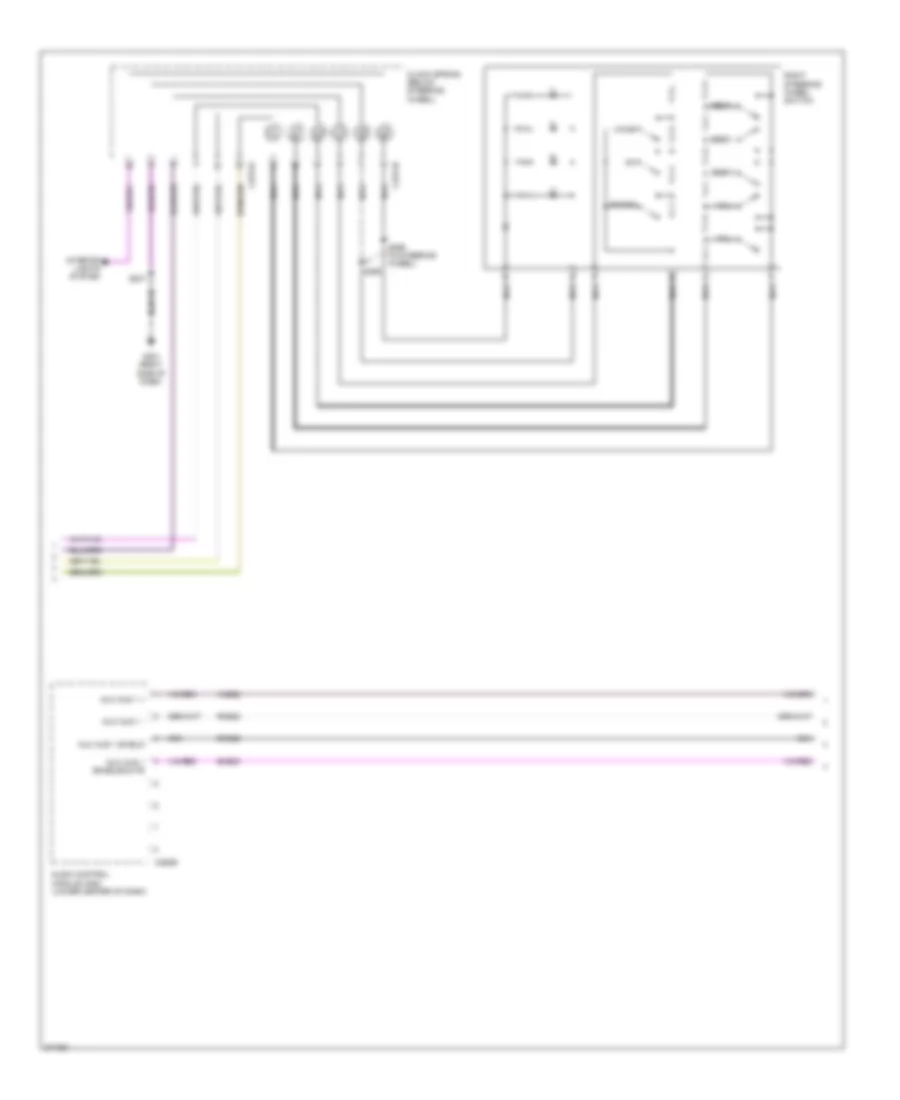
Premium Radio Wiring Diagram, with Navigation (3 of 4) for Ford Mustang Shelby GT500 2012
List of elements for Premium Radio Wiring Diagram, with Navigation (3 of 4) for Ford Mustang Shelby GT500 2012:
- Audio control module (acm) (lower center of dash)
- Aux aud 1 +
- Aux aud 1 -
- Aux aud 1 enable/mute
- Aux aud 1 shield
- C2274a
- C2274b
- C290b
- Clock spring (below steering wheel)
- Dme22
- G201 (right side of dash)
- Interior lights system
- Media
- Nca
- Phone
- Right steering wheel switch
- Rme22
- S201
- S298
- S299 (in steering wheel)
- Seek+
- Seek-
- Sme23
- Vme22
- Voice
- Vol+
- Vol-
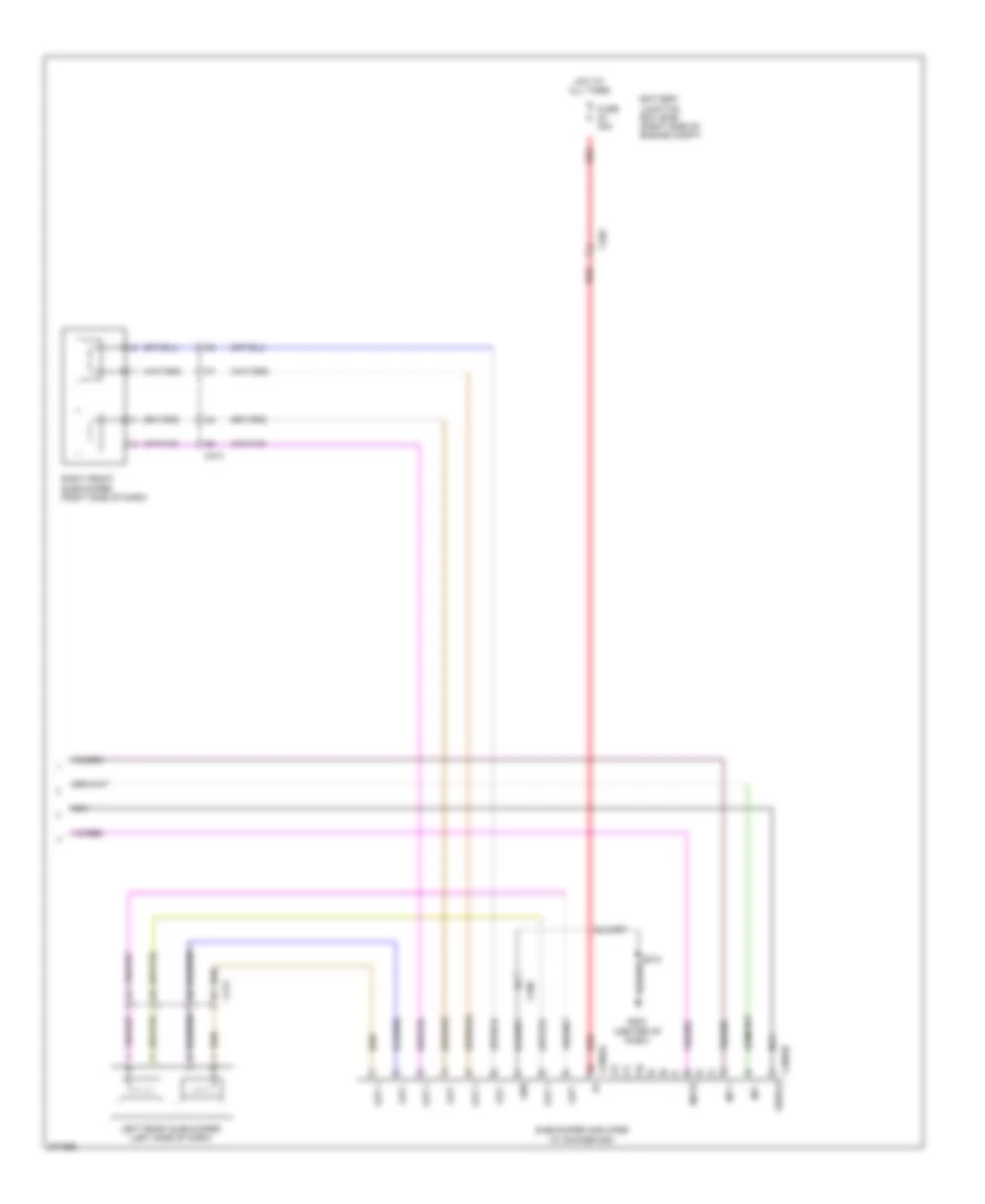
Premium Radio Wiring Diagram, with Navigation (4 of 4) for Ford Mustang Shelby GT500 2012
List of elements for Premium Radio Wiring Diagram, with Navigation (4 of 4) for Ford Mustang Shelby GT500 2012:
- (center of dash)
- Battery junction box (bjb) (right side of engine compt)
- C213
- C214
- C260
- C265
- C2982a
- C2982b
- Fuse 30a
- G202
- Gnd
- Hot at all times
- Inp +
- Inp -
- Left front subwoofer (left side of dash)
- Mute
- Nca
- Out +
- Out -
- Red
- Right front subwoofer (right side of dash)
- S210
- Shield
- Subwoofer amplifier (w/ shaker 500)
Premium Radio Wiring Diagram, without Navigation (1 of 2) for Ford Mustang Shelby GT500 2012
List of elements for Premium Radio Wiring Diagram, without Navigation (1 of 2) for Ford Mustang Shelby GT500 2012:
- Ant
- Antenna
- Audio control module (acm) (lower center of dash)
- Audio input jack (w/o sync)
- Aux aud 2 +
- Aux aud 2 -
- C210
- C213
- C214
- C2280a
- C2280b
- C260
- C290a
- C290b
- C290d
- Cme44
- Coaxial cable
- Computer data lines system
- Dme35
- Dme45
- Dme51
- Drain
- Fuse 20a
- Fuse 5a
- G202 (center of dash)
- Gd115
- Hot at all times
- Hot in start
- Left door speaker
- Left quarter panel speaker
- Lf spkr +
- Lf spkr -
- Lr spkr +
- Lr spkr -
- Mono out +
- Mono out -
- Ms can +
- Ms can -
- Nca
- Rf spkr +
- Rf spkr -
- Right door speaker
- Right quarter panel speaker
- Rme07
- Rme09
- Rme10
- Rme12
- Rme14
- Rme45
- Rme46
- Rme51
- Rme52
- Rme53
- Rmn14
- Rr spkr +
- Rr spkr -
- S210
- Sbp28
- Sbp39
- Shield aux aud 2 enable/mute
- Smart junction box (sjb) (right kick panel)
- Sme51
- St input 2l+
- St input 2l-
- St input 2r+
- St input 2r-
- Start
- Stereo 1 l+
- Stereo 1 l-
- Stereo 1 rt+
- Stereo 1 rt-
- Stereo 2 r+
- Stereo 2 r-
- Stereo in lt+
- Stereo in lt-
- Swc1+
- Swc1-
- Sync radio circuit
- System gnd
- Vdb06
- Vdb07
- Vme07
- Vme09
- Vme10
- Vme12
- Vme14
- Vme35
- Vme45
- Vme46
- Vme51
- Vme52
- Vme53
- Vmn14
Premium Radio Wiring Diagram, without Navigation (2 of 2) for Ford Mustang Shelby GT500 2012
List of elements for Premium Radio Wiring Diagram, without Navigation (2 of 2) for Ford Mustang Shelby GT500 2012:
- 1 +
- 1 -
- 2 +
- 2 -
- 3 +
- 3 -
- 4 +
- 4 -
- Battery junction box (bjb) (right side of engine compt)
- C2274a
- C2274b
- C2280b
- C237
- C4109
- Clock spring (below steering wheel)
- Computer data lines system
- Front controls interface module (fcm) (lower center of dash)
- Front display interface module (fdim)
- Fuse 10a
- Fuse 30a
- G201 (right side of dash)
- G202 (center of dash)
- G401 (rear center of luggage compt)
- Gd115
- Gd116
- Gnd
- Hot at all times
- Inp +
- Inp -
- Media
- Ms can +
- Ms can -
- Mute
- Nca
- Rear a subwoofer
- Rear b subwoofer
- Rear subwoofer amplifier (w/ shaker 1000) (right rear of luggage compt)
- Right steering wheel switch
- S201
- S210
- Sbp14
- Seek +
- Seek -
- Smart junction box (sjb) (right kick panel)
- Vbatt
- Vdb06
- Vdb07
- Vol +
- Vol -
SYNC Radio Wiring Diagram (1 of 2) for Ford Mustang Shelby GT500 2012
List of elements for SYNC Radio Wiring Diagram (1 of 2) for Ford Mustang Shelby GT500 2012:
- (w/ navigation)
- Accessory protocol interface module (apim) (right side of dash)
- Audio input jack
- Auto dimming interior mirror unit
- C210
- C2280a
- C2280b
- C2280d
- C919
- Computer data lines system
- Dme45
- Dme52
- Dmm23
- Dmn14
- Drain wire
- Front display interface module (fdim) (w/o navigation)
- Fuse 14 10a
- Fuse 3 15a
- Fuse 39 20a
- G201 (right side of dash)
- G202 (center of dash)
- Gd115
- Gd116
- Gnd
- Hot at all times
- Hs can +
- Hs can -
- Left +
- Left -
- Mic in +
- Mic in -
- Mic out +
- Mic out -
- Mono out +
- Mono out -
- Ms can +
- Ms can -
- Nca
- Right +
- Right -
- Rme45
- Rme46
- Rme52
- Rme53
- Rme54
- Rmm13
- Rmm23
- Rmn14
- S201
- S210
- S232
- Sbp03
- Sbp14
- Shield
- Smart junction box (sjb) (right kick panel)
- St input 2l +
- St input 2l -
- St input 2r +
- St input 2r -
- Swc2 +
- Swc2 -
- Usb
- Usb cable
- Usb port
- Vbatt
- Vdb04
- Vdb05
- Vdb06
- Vdb07
- Vme45
- Vme46
- Vme52
- Vme53
- Vme54
- Vmm13
- Vmm23
- Vmn14
- W/ rear view camera & w/o navigation
- W/o rear view camera
SYNC Radio Wiring Diagram (2 of 2) for Ford Mustang Shelby GT500 2012
List of elements for SYNC Radio Wiring Diagram (2 of 2) for Ford Mustang Shelby GT500 2012:
- (w/ navigation)
- Ant
- Antenna
- Audio control module (acm) (lower center of dash)
- C210
- C2274a
- C2274b
- C290a
- C290d
- Clockspring (below steering wheel)
- Cme44
- Coaxial cable
- Computer data lines system
- Dme35
- Dme41
- Dmn03
- Front controls interface module (fcim) (lower center of dash)
- G202 (center of dash)
- Gd115
- Global positioning system module (gpsm) (w/o navigation) (right side of dash)
- Gnd
- Gps
- Gps/sdars
- Gps/sdars splitter (w/ sdars)
- Interior lights system
- Mic out +
- Mic out -
- Mono out +
- Mono out -
- Ms can +
- Ms can -
- Ms can+
- Ms can-
- Nca
- Phone
- Right steering wheel switch
- Rme52
- Rme53
- Rme54
- Rmm23
- Rmn14
- S210
- Sbp14
- Sbp39
- Sdars
- Stereo 1 rt+
- Stereo 1 rt-
- Stereo in lt+
- Stereo in lt-
- Swc2 +
- Swc2 -
- System gnd
- Vbatt
- Vdb06
- Vdb07
- Vme35
- Vme43
- Vme52
- Vme53
- Vme54
- Vmm23
- Vmn03
- Vmn14
- Voice
- W/ navigation
- W/o navigation

 Čeština
 Dansk
Dansk Deutsch
 Ελληνικά
 English
 Español
 Suomi
Suomi Français
 Français
 עברית
עברית Hrvatski
 Magyar
 Italiano
 日本語
日本語 한국어
한국어 Nederlands
 Polski
 Português
 Português
 Română
 Русский
 Slovenčina
 Slovenščina
 Svenska
 Türkçe
 中文 (中国)