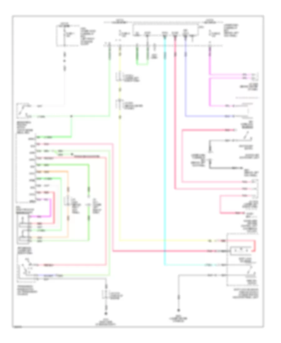
SHIFT INTERLOCK
Shift Interlock Wiring Diagram for Acura MDX 2011
List of elements for Shift Interlock Wiring Diagram for Acura MDX 2011:
- (not used)
- A16
- A18
- A19
- A24
- A25
- A26
- A27
- Acc+
- App sensor (under left side of dash)
- Apsa
- Apsb
- Atpn
- Atpp
- Bksw
- Brake pedal position switch (top of brake pedal arm)
- C26
- F12
- Fuse 11 15a
- Fuse 21 7.5a
- Fuse 32 10a
- G101 (right side of engine compt)
- G503 (under center console)
- G601 (behind left kick panel)
- Hot at all times
- Hot in acc or on
- Hot in on or start
- Ig key sw
- Ig key sw p13
- Ig1 mtr
- Ignition key switch
- Ignition key switch/key light
- Immobilizer keyless control unit (in steering column)
- J/c c104 (middle of engine)
- J/c c208 (behind right kick panel)
- J/c c211 (under left side of dash)
- J/c c514 (under left side of dash)
- J/c c516 (under left side of dash)
- J/c c521 (behind center of dash)
- J/c c526 (behind center of dash)
- Key interlock solenoid
- Key lock sol p15
- Main under-hood fuse/relay box (left front of engine compt)
- Micu
- N18
- N21
- N26
- N37
- N39
- P-pin sw p2
- Park pin switch
- Pcm (right front of engine compt)
- Pnk
- Red
- Sg3
- Sg4
- Shift lock solenoid
- Shift lock solenoid/ park pin switch/ a/t gear position indicator panel light
- Sls
- Stop sw
- Transmission range switch (on transmission housing)
- Transmissions system
- Under-dash fuse/relay box (behind left kick panel)
- Vcc3
- Vcc4
- X34
 Čeština
 Dansk
Dansk Deutsch
 Ελληνικά
 English
 Español
 Suomi
Suomi Français
 Français
 עברית
עברית Hrvatski
 Magyar
 Italiano
 日本語
日本語 한국어
한국어 Nederlands
 Polski
 Português
 Português
 Română
 Русский
 Slovenčina
 Slovenščina
 Svenska
 Türkçe
 中文 (中国)
 English