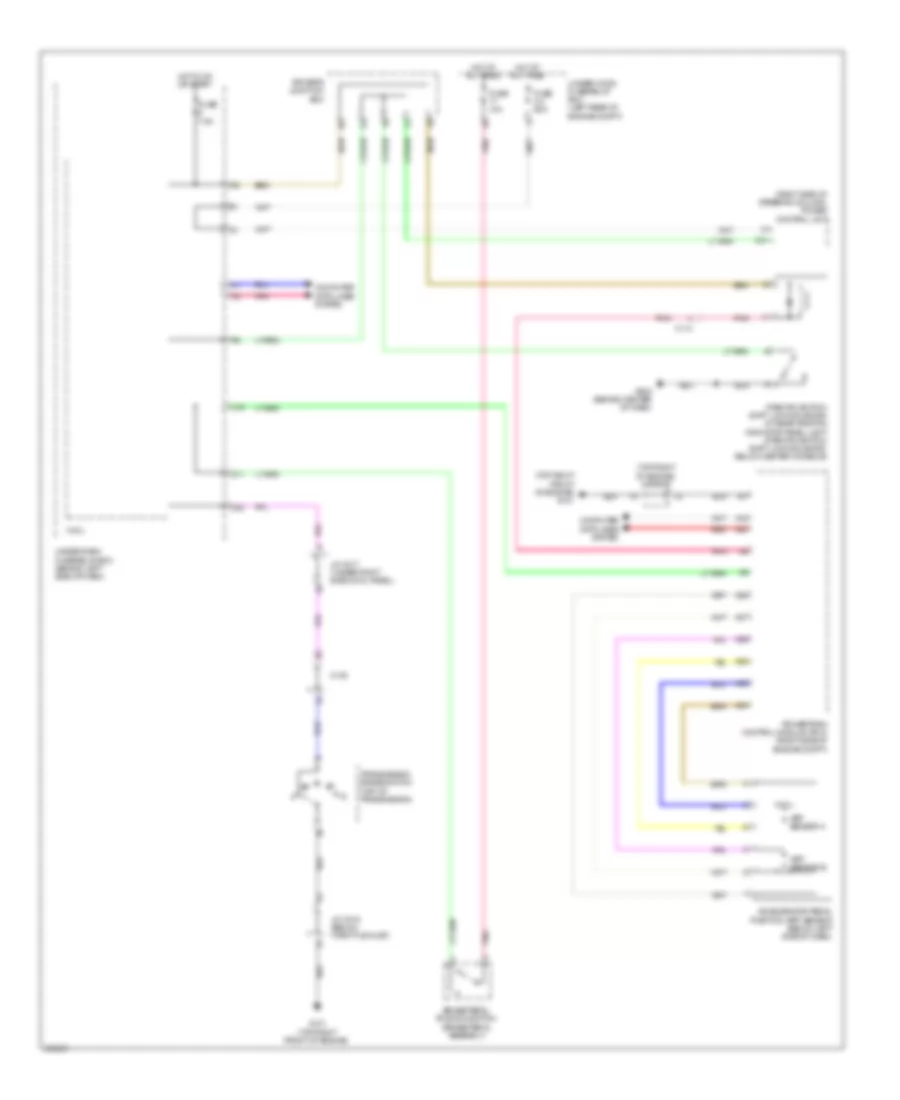
SHIFT INTERLOCK
Shift Interlock Wiring Diagram for Acura RDX 2014
List of elements for Shift Interlock Wiring Diagram for Acura RDX 2014:
- (right side of steering column) power control unit
- (top right front of engine) g101
- (top right of engine) j/c c013
- A19
- A20
- A28
- A29
- A34
- A35
- A36
- A37
- Accelerator pedal position (app) sensor (below left side of dash)
- App sensor a
- App sensor b
- Brake pedal position switch (brake pedal assembly)
- C114
- C139
- C16
- C31
- Computer data lines system
- D11
- D22
- Driver's junction box
- Fuse 10a
- Fuse 2-4 50a
- Fuse 7.5a
- G101 (top right front of engine)
- G503 (behind center of dash)
- Hot at all times
- Hot in on or start
- J/c c015 (below throttle inlet)
- J/c c017 (under right side cowl panel)
- Micu
- Park pin switch/ shift lock solenoid/ a/t gear position indicator panel light (park pin switch/ shift lock solenoid: below center console)
- Pnk
- Powertrain control module (pcm) (right side of engine compt)
- Red
- Transmission range switch (top of transmission)
- Under-dash fuse/relay box (behind left side of dash)
- Under-hood fuse/relay box (left rear of engine compt)
 Čeština
 Dansk
Dansk Deutsch
 Ελληνικά
 English
 English
 Español
 Suomi
Suomi Français
 Français
 עברית
עברית Hrvatski
 Italiano
 日本語
日本語 한국어
한국어 Nederlands
 Polski
 Português
 Português
 Română
 Русский
 Slovenčina
 Slovenščina
 Svenska
 Türkçe
 中文 (中国)
 Magyar