SHIFT INTERLOCK
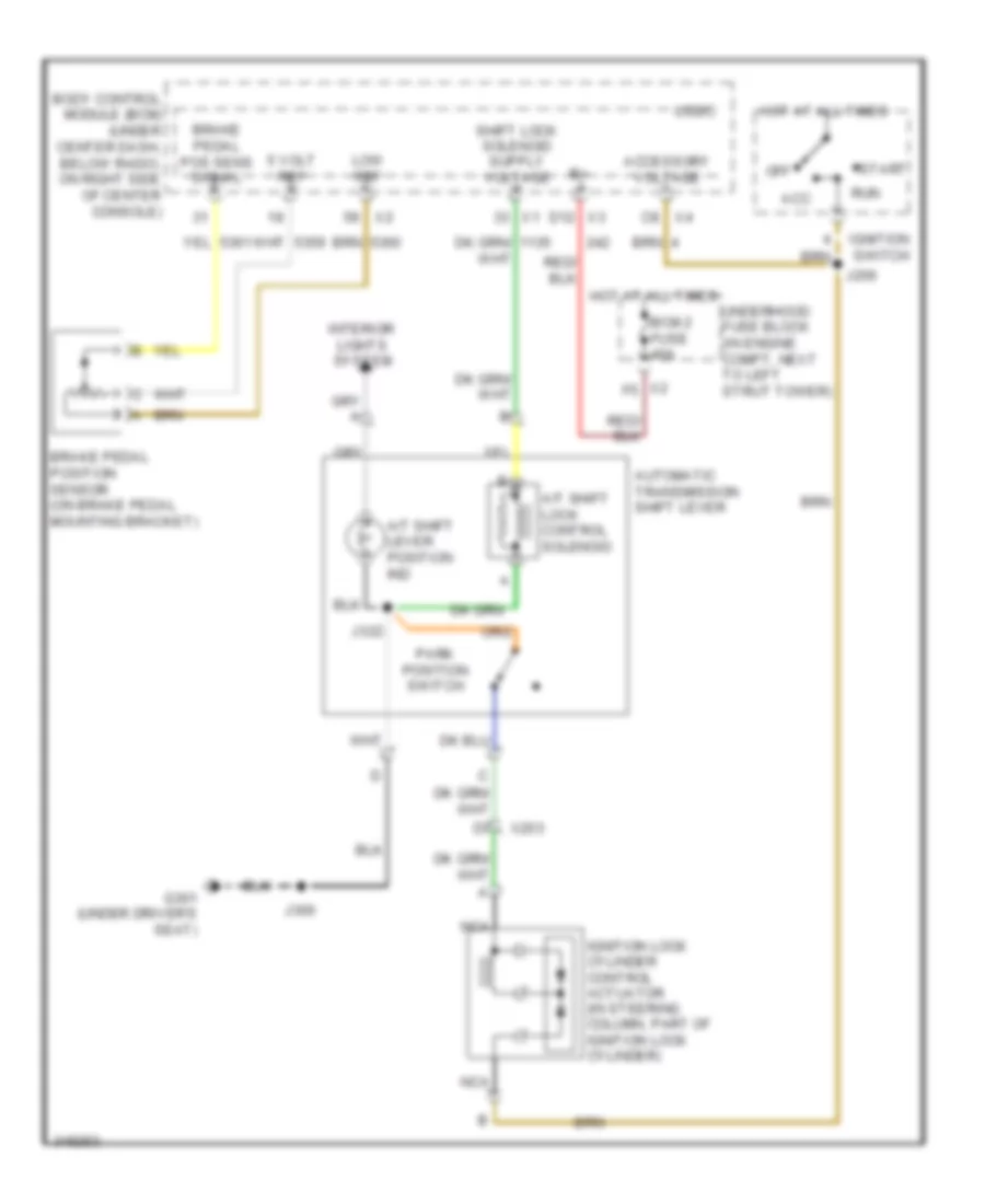
Shift Interlock Wiring Diagram for Chevrolet HHR LT 2011
List of elements for Shift Interlock Wiring Diagram for Chevrolet HHR LT 2011:
- 5 volt ref
- A/t shift lever position ind
- A/t shift lock control solenoid
- Acc
- Accessory voltage
- Automatic transmission shift lever
- Bcm 2 fuse 40a
- Body control module (bcm) (under center dash, below radio, on right side of center console)
- Brake pedal pos sens signal
- Brake pedal position sensor (on brake pedal mounting bracket)
- C8 x4
- D12 x3
- G301 (under driver's seat)
- Hot at all times
- Ignition lock cylinder control actuator (in steering column, part of ignition lock cylinder)
- Ignition switch
- Interior lights system
- J206
- J300
- J322
- Logic
- Low ref
- Nca
- Off
- Park position switch
- Run
- Start
- Underhood fuse block (in engine compt, next to left strut tower)
- X2 f5
- X203
 Čeština
 Dansk
Dansk Deutsch
 Ελληνικά
 English
 Español
 Suomi
Suomi Français
 Français
 עברית
עברית Hrvatski
 Magyar
 Italiano
 日本語
日本語 한국어
한국어 Nederlands
 Polski
 Português
 Português
 Română
 Русский
 Slovenčina
 Slovenščina
 Svenska
 Türkçe
 中文 (中国)
 English