SHIFT INTERLOCK
3.7L
3.7L, Shift Interlock Wiring Diagram for Dodge Nitro Detonator 2011
 https://portal-diagnostov.com/license.html
Automotive Electricians Portal FZCO
Automotive Electricians Portal FZCO
https://portal-diagnostov.com/license.html
https://portal-diagnostov.com/license.html
Automotive Electricians Portal FZCO
Automotive Electricians Portal FZCO
List of elements for 3.7L, Shift Interlock Wiring Diagram for Dodge Nitro Detonator 2011:
- Batt fd
- Batt fd 9
- Btsi sol ulk
- C201
- Can c bus (+)
- Can c bus (-)
- Can int bus (+)
- Can int bus (-)
- Cluster
- Computer data lines system
- D64
- D65
- Dim sig
- Fuse m1 15a
- Fuse m20 15a
- G201 (left kick panel)
- Gnd
- Hot at all times
- Interior lights system
- Powertrain control module (right rear of engine compt)
- Prk/neut sig
- Red
- S213
- S220
- Shift lever assembly
- Stop lamp switch (top of brake pedal assembly)
- Stp lp sig
- Sw ovr drv sig
- T41
- T42
- Totally integrated power module (left side of engine compt)
- Transmission range sensor (left side of transmission)
- Trs c2 sig
- Trs c3 sig
- Trs c4 sig
- Trs rng c2 sig
- Trs rng c3 sig
- Trs rng c4 sig
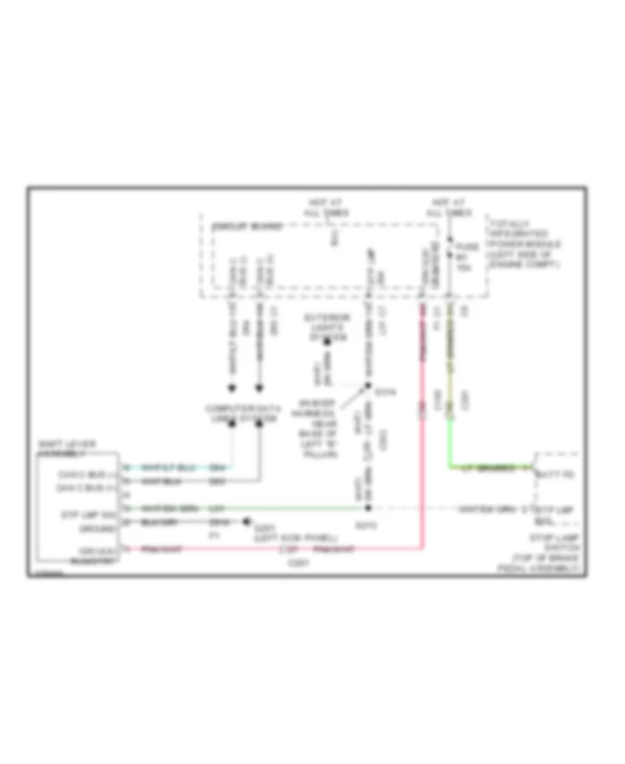
4.0L
4.0L, Shift Interlock Wiring Diagram for Dodge Nitro Detonator 2011
List of elements for 4.0L, Shift Interlock Wiring Diagram for Dodge Nitro Detonator 2011:
- (in body harness, near base of left "b" pillar)
- B(+)
- Batt fd
- C105
- C201
- C202
- Can c bus (+)
- Can c bus (-)
- Circuit board
- Computer data lines system
- D64
- D65
- Exterior lights system
- Fuse m1 15a
- G201 (left kick panel)
- Ground
- Hot at all times
- Ign ulk/ run/strt
- L51
- S213
- S314
- Shift lever assembly
- Stop lamp switch (top of brake pedal assembly)
- Stp lmp sig
- Sw stp lmp
- Totally integrated power module (left side of engine compt)
- Z910

 Čeština
 Dansk
Dansk Deutsch
 Ελληνικά
 English
 English
 Español
 Suomi
Suomi Français
 Français
 עברית
עברית Hrvatski
 Magyar
 Italiano
 日本語
日本語 한국어
한국어 Nederlands
 Português
 Português
 Română
 Русский
 Slovenčina
 Slovenščina
 Svenska
 Türkçe
 中文 (中国)