SHIFT INTERLOCK
Shift Interlock Wiring Diagram, with Console for Ford Crown Victoria LX 2007
 https://portal-diagnostov.com/license.html
Automotive Electricians Portal FZCO
Automotive Electricians Portal FZCO
https://portal-diagnostov.com/license.html
https://portal-diagnostov.com/license.html
Automotive Electricians Portal FZCO
Automotive Electricians Portal FZCO
List of elements for Shift Interlock Wiring Diagram, with Console for Ford Crown Victoria LX 2007:
- (behind left kick panel) g212
- (behind right kick panel) g204
- Battery junction box (bjb) (right front of engine compartment, behind battery)
- Brake pedal position switch (top of brake pedal support)
- Brake shift interlock (on steering column)
- Central junction box (cjb) (below dash, left of steering column)
- Fuse 10a
- Fuse 20a
- Fuse 7.5a
- Hot at all times
- Hot in start or run
- Red
- S204
- S230
- S246
- S267
- Solid state
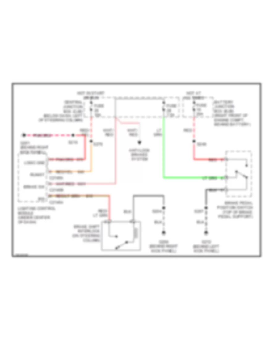
Shift Interlock Wiring Diagram, without Console for Ford Crown Victoria LX 2007
List of elements for Shift Interlock Wiring Diagram, without Console for Ford Crown Victoria LX 2007:
- Anti-lock brakes system
- Battery junction box (bjb) (right front of engine compt, behind battery)
- Brake pedal position switch (top of brake pedal support)
- Brake shift interlock (on steering column)
- Brake sw
- Bsi
- C2145a
- C2145b
- Central junction box (cjb) (below dash, left of steering column)
- Fuse 10a
- Fuse 20a
- Fuse 7.5a
- G201 (behind right kick panel)
- G204 (behind right kick panel)
- G212 (behind left kick panel)
- Hot at all times
- Hot in start or run
- Lighting control module (under center of dash)
- Logic gnd
- Red
- Run/st
- S204
- S210
- S246
- S267
- S276

 Čeština
 Dansk
Dansk Deutsch
 Ελληνικά
 English
 Español
 Suomi
Suomi Français
 Français
 עברית
עברית Hrvatski
 Magyar
 Italiano
 日本語
日本語 한국어
한국어 Nederlands
 Polski
 Português
 Português
 Română
 Русский
 Slovenčina
 Slovenščina
 Svenska
 Türkçe
 中文 (中国)