SHIFT INTERLOCK
Shift Interlock Wiring Diagram for Ford Escape 2004
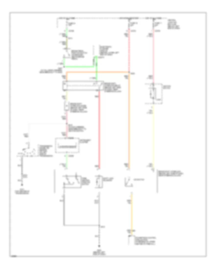
List of elements for Shift Interlock Wiring Diagram for Ford Escape 2004:
- Brake pedal position switch (on bracket, above brake pedal)
- Brake shift interlock diode (behind left side of dash, near steering column)
- Brake shift interlock (behind left side of dash, near steering column)
- Brake shift interlock relay (behind left side of dash, near steering column)
- C2027a
- C220b
- C270c
- C270d
- C270e
- Central junction box (cjb) (below left end of dash)
- Electronic flasher module (behind lower left end of dash)
- Fuse 11 10a
- Fuse 16 10a
- Fuse 24 15a
- G101 (top center of transmission)
- G203 (behind left side of dash)
- Hot at all times
- Hot in run or start
- Ignition switch
- Instrument cluster
- Lock
- Microprocessor
- O/d switch
- Park neutral position switch
- Powertrain control module (pcm) (in recess on upper center of firewall)
- Red
- S104 (2.0l)
- S212
- S218 (in main harness, near breakout to ignition switch)
- S222
- S314
- S407 (in taillamps harness, near breakout to g402)
- Shift lock solenoid
- Transmission range (tr) sensor (on left side of transmission)
 Čeština
 Dansk
Dansk Deutsch
 Ελληνικά
 English
 Español
 Suomi
Suomi Français
 Français
 עברית
עברית Hrvatski
 Magyar
 Italiano
 日本語
日本語 한국어
한국어 Nederlands
 Polski
 Português
 Português
 Română
 Русский
 Slovenčina
 Slovenščina
 Svenska
 Türkçe
 中文 (中国)
 English