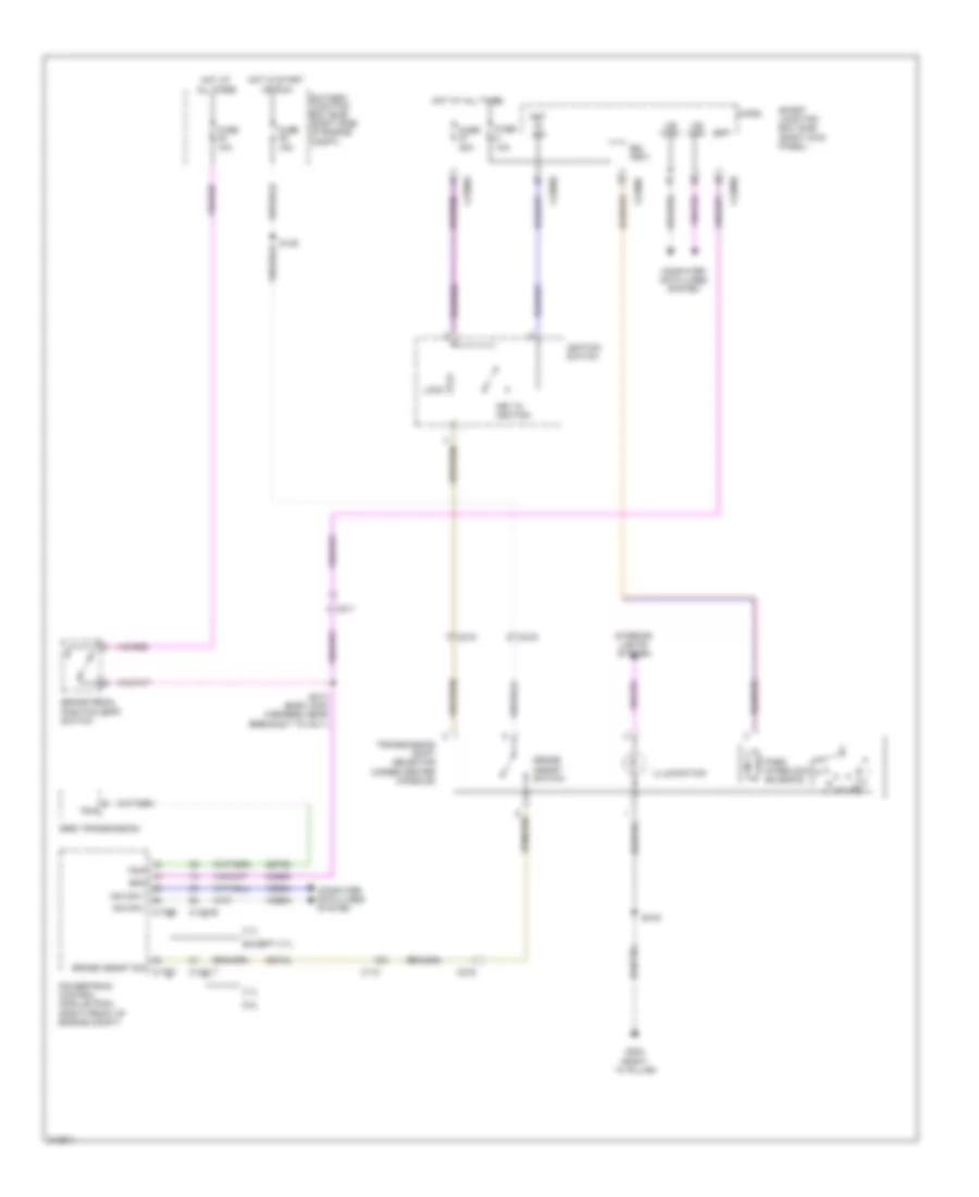
SHIFT INTERLOCK
Shift Interlock Wiring Diagram for Ford Mustang Shelby GT500 2011
List of elements for Shift Interlock Wiring Diagram for Ford Mustang Shelby GT500 2011:
- (right ``a" pillar)
- 3.7l
- 5.0l
- 6r80 transmission
- All times
- Battery junction box (bjb) (right side of engine compt)
- Boo
- Bpp
- Brake pedal position (bpp) switch
- Bsi (fet)
- C110
- C1381b
- C1381t
- C210
- C211
- C219
- C2280a
- C2280b
- C2280c
- Ccb08
- Cet34
- Cet60
- Computer data lines system
- Except 3.7l
- Fuse 10a
- Fuse 15a
- Fuse 20a
- G203
- Grade assist sw c175t
- Grade assist switch
- Hot at
- Hot at all times
- Hot in start
- Hs can +
- Hs can - c175b
- Ignition switch
- Illumination
- Interior lights system
- Key in ign
- Key in ignition
- Lock
- Micro
- Ms can+
- Ms can-
- Or run
- Park interlock solenoid
- Powertrain control module (pcm) (right front of engine compt)
- S125
- S213 (body main harness, near breakout to c211)
- S319
- Smart junction box (sjb) (right kick panel)
- Tr-p
- Transmission shift selector (under center console)
- Vdb04
- Vdb05
 Čeština
 Dansk
Dansk Deutsch
 Ελληνικά
 English
 Español
 Suomi
Suomi Français
 Français
 עברית
עברית Hrvatski
 Magyar
 Italiano
 日本語
日本語 한국어
한국어 Nederlands
 Polski
 Português
 Português
 Română
 Русский
 Slovenčina
 Slovenščina
 Svenska
 Türkçe
 中文 (中国)
 English