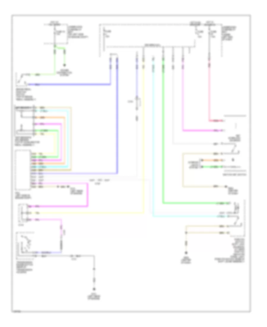
SHIFT INTERLOCK
Shift Interlock Wiring Diagram for Honda CR-V EX-L 2014
List of elements for Shift Interlock Wiring Diagram for Honda CR-V EX-L 2014:
- A13
- A21
- A28
- A29
- A35
- A36
- A45
- A46
- App sensor a
- App sensor b app sensor (top of accelerator pedal assembly)
- B24
- Brake pedal position switch (top of brake pedal assembly)
- C10
- C105
- C13
- C131
- C134
- C16
- C20
- D11
- D22
- Driver's micu
- Fuse 10a
- Fuse 15a
- Fuse 16 10a
- Fuse 7.5a
- G101 (left rear of engine)
- G502 (center of dash)
- Hot at all times
- Hot in acc or on
- Hot in on or start
- Ignition key switch
- Interior lights system
- Key interlock solenoid
- P10
- P11
- Park pin switch/ shift lock solenoid/ a/t gear position indicator panel light (park pin switch: base of shift lever assembly)
- Pcm (left side of engine compt)
- Pnk
- Power distribution system
- Transmission range switch (rear of transmission housing)
- Under-dash fuse/relay box (under left end of dash)
- Under-hood fuse/relay box (on left side of engine compt)
 Čeština
 Dansk
Dansk Deutsch
 Ελληνικά
 English
 Español
 Suomi
Suomi Français
 Français
 עברית
עברית Hrvatski
 Magyar
 Italiano
 日本語
日本語 한국어
한국어 Nederlands
 Polski
 Português
 Português
 Română
 Русский
 Slovenčina
 Slovenščina
 Svenska
 Türkçe
 中文 (中国)
 English