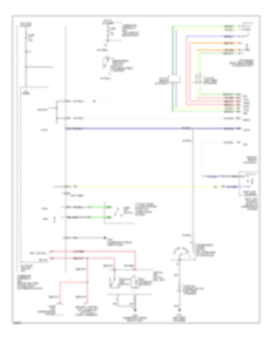
SHIFT INTERLOCK
Shift Interlock Wiring Diagram for Honda Element LX 2010
List of elements for Shift Interlock Wiring Diagram for Honda Element LX 2010:
- (not used)
- (under middle
- A/t shift lever illumination/park pin switch
- A20
- A21
- A23
- A24
- A25
- A26
- App sensor (right rear corner of engine compt)
- Apsa
- Apsb
- Atp-p
- Bksw
- Brake pedal position switch (on brake pedal support)
- D10
- D11
- E22
- Ecm/pcm (behind glove box)
- Fuse 15a
- Fuse 7.5a
- G101 (left rear of engine)
- G401 (under right middle side of dash)
- Gnd
- Hot at all times
- Hot in on or start
- Ig1 meter
- Ignition key switch
- Ignition key switch/ key light
- Imoes unit (under center of dash)
- J/c c105 (left rear of engine)
- J/c c107 (behind glove box)
- Junction connector c106 (left rear of engine)
- Key interlock solenoid
- Key lock sol +
- Key sw
- Multiplex control unit
- Of dash)
- P-pin
- Park pin switch
- Security control unit connector (optional & honda accessory)
- Sg1
- Sg2
- Shift lock solenoid
- Shift lock solenoid/ d3 switch (under middle of dash)
- Sls
- Stop sw
- Transmission range switch (on lower rear of transaxle)
- Under-hood fuse/relay box (left rear of engine compt)
- Underdash fuse/relay box (behind left side of dash, right of steering column)
- Vcc1
- Vcc2
 Čeština
 Dansk
Dansk Deutsch
 Ελληνικά
 English
 Español
 Suomi
Suomi Français
 Français
 עברית
עברית Hrvatski
 Magyar
 Italiano
 日本語
日本語 한국어
한국어 Nederlands
 Polski
 Português
 Português
 Română
 Русский
 Slovenčina
 Slovenščina
 Svenska
 Türkçe
 中文 (中国)
 English