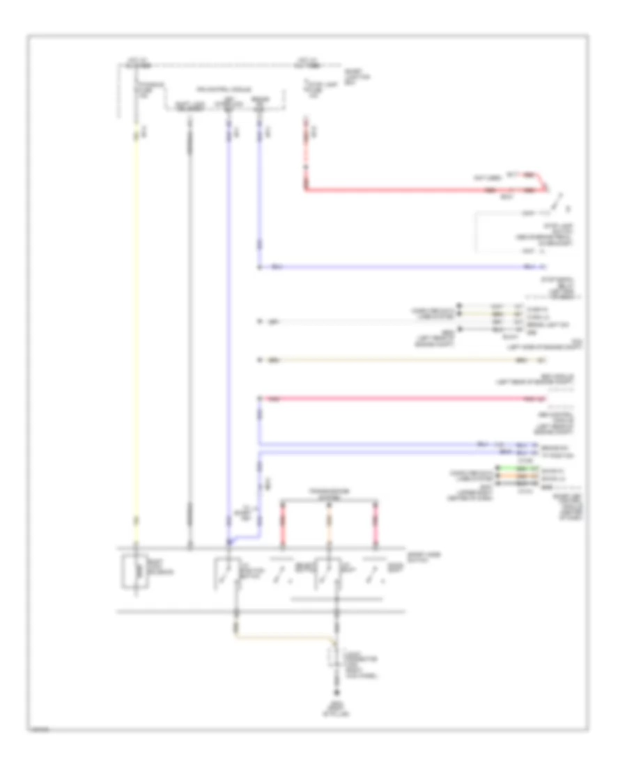
SHIFT INTERLOCK
Shift Interlock Wiring Diagram for Hyundai Azera 2014
List of elements for Shift Interlock Wiring Diagram for Hyundai Azera 2014:
- "p"
- "p" position
- (not used)
- Abs control module (left rear of engine compt)
- B-can hi
- B-can lo
- Brake light sw
- Brake sw
- Brake sw (n.o)
- C-can hi
- C-can lo
- Computer data lines system
- Down shift
- Elg-a
- Em31
- Esc module (left rear of engine compt)
- Ge05 (left rear of engine compt)
- Gf03 (right "b" pillar)
- Gm07 (upper right center of dash)
- Gnd
- Hot at all times
- I/p-a
- I/p-c
- I/p-d
- I/p-f
- Ips control module
- Joint connector jf05 (right kick panel)
- Key
- Key interlock sw
- M13-a
- M13-b
- Mf21
- P/handle fuse 15a
- Pcm (left side of engine compt)
- Pnk
- Position switch
- Red
- Select switch
- Shift lock solenoid
- Smart
- Smart junction box
- Smart key control module (center of dash)
- Sport mode switch
- Stop lamp fuse 10a
- Stop lamp switch (above brake pedal, on bracket)
- Stop signal relay (left end of dash)
- Transmissions system
- Up shift
 Čeština
 Dansk
Dansk Deutsch
 Ελληνικά
 English
 Español
 Suomi
Suomi Français
 Français
 עברית
עברית Hrvatski
 Magyar
 Italiano
 日本語
日本語 한국어
한국어 Nederlands
 Polski
 Português
 Português
 Română
 Русский
 Slovenčina
 Slovenščina
 Svenska
 Türkçe
 中文 (中国)
 English