SHIFT INTERLOCK
Electric Parking Brake Wiring Diagram for Hyundai Elantra GT 2013
 https://portal-diagnostov.com/license.html
Automotive Electricians Portal FZCO
Automotive Electricians Portal FZCO
https://portal-diagnostov.com/license.html
https://portal-diagnostov.com/license.html
Automotive Electricians Portal FZCO
Automotive Electricians Portal FZCO
List of elements for Electric Parking Brake Wiring Diagram for Hyundai Elantra GT 2013:
- B-can transceiver
- C-can high
- C-can low
- C-can transceiver
- Clutch 1 gnd
- Clutch 1 pwr
- Clutch 1 sig
- Clutch 2 gnd
- Clutch 2 pwr
- Clutch 2 sig
- Clutch sensor (m/t) (left rear of dash)
- Computer data lines system
- E/r fuse & relay box (in left rear corner of engine compt)
- Ec02
- Ec11
- Ef11
- Ef31
- Electric parking brake switch
- Electronic parking brake module (rear of center console)
- Epb 1 fuse 30a
- Epb 2 fuse 30a
- Epb ind
- Ff01
- Gf06 (under rear seat)
- Gng02
- Ground
- High
- Hot at all times
- Hot in on or start
- I/p-b
- I/p-h
- Ill
- Instrument cluster
- Interface
- Interior lights system
- Left electronic parking brake actuator
- Left motor (+)
- Left motor (-)
- Low
- Memory pwr
- Micom
- Module 2 fuse 7.5a
- Module 3 fuse 7.5a
- Nca
- Neutral switch
- Neutral switch (m/t)
- On/start input
- Pnk
- Power distribution system
- Red
- Right electric parking brake actuator
- Right motor (+)
- Right motor (-)
- Smart junction box (under left side of dash, near kick panel)
- Sw 1
- Sw 2
- Sw 2 release
- Sw 3
- Sw 4
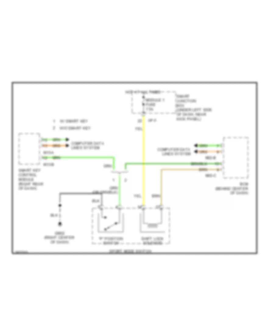
Shift & Key Lock Wiring Diagram for Hyundai Elantra GT 2013
List of elements for Shift & Key Lock Wiring Diagram for Hyundai Elantra GT 2013:
- "p" position switch
- Bcm (behind center of dash)
- Computer data lines system
- Gm02 (right center of dash)
- Hot at all times
- I/p-f
- M02-b
- M02-c
- M13-a
- M13-b
- Module 1 fuse 7.5a
- Shift lock solenoid
- Smart junction box (under left side of dash, near kick panel)
- Smart key control module (right rear of dash)
- Sport mode switch
- W/ smart key
- W/o smart key

 Dansk
Dansk Deutsch
 Ελληνικά
 English
 English
 Español
 Suomi
Suomi Français
 Français
 עברית
עברית Hrvatski
 Magyar
 Italiano
 日本語
日本語 한국어
한국어 Nederlands
 Polski
 Português
 Português
 Română
 Русский
 Slovenčina
 Slovenščina
 Svenska
 Türkçe
 中文 (中国)