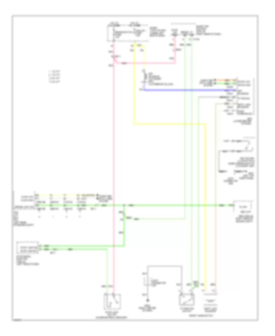
SHIFT INTERLOCK
Shift Interlock Wiring Diagram for Hyundai Elantra Limited 2014
List of elements for Shift Interlock Wiring Diagram for Hyundai Elantra Limited 2014:
- "p" pos
- "p" pos sw
- "p" position switch
- (lower center
- (or pnk)
- (right center of dash)
- 1.8l a/t
- 1.8l m/t
- 2.0l a/t
- 2.0l m/t
- B-can high
- B-can low
- Bcm
- Brake light sw
- Brake sig
- Brake switch fuse 10a
- C-can high
- C-can low
- C100-ak
- C100-ma
- C100-mk
- C600-ab
- C600-mk
- Computer data lines system
- Door warning sw
- Ec11
- Em11
- Em61
- Esc module (right rear of engine compt)
- Esc unit
- Gm01 (left top dash panel)
- Gm02
- Hot at all times
- I/p-f
- Ignition key illumination & door warning switch (w/o smart key)
- Joint connector ume
- Joint connector umf
- Key solenoid
- Key solenoid (w/o smart key) (in steering column)
- M02-a
- M02-b
- M02-c
- M13-b
- Module 1 fuse 7.5a
- Nca
- Of dash)
- Pcm (a/t) ecm (m/t) (left rear of engine compt)
- Pnk
- Red
- Rl sig
- Shift lock solenoid
- Smart junction box (under left end of dash)
- Smart key control module (right rear of dash)
- Sport mode switch
- Stop lamp sig
- Stop lamp sw
- Stop lamp switch (on brake pedal bracket)
- Stop lmp pwr
- Stop signal electric module (left side of dash)
 Čeština
 Dansk
Dansk Deutsch
 Ελληνικά
 English
 Español
 Suomi
Suomi Français
 Français
 עברית
עברית Hrvatski
 Magyar
 Italiano
 日本語
日本語 한국어
한국어 Nederlands
 Polski
 Português
 Português
 Română
 Русский
 Slovenčina
 Slovenščina
 Svenska
 Türkçe
 中文 (中国)
 English