SHIFT INTERLOCK
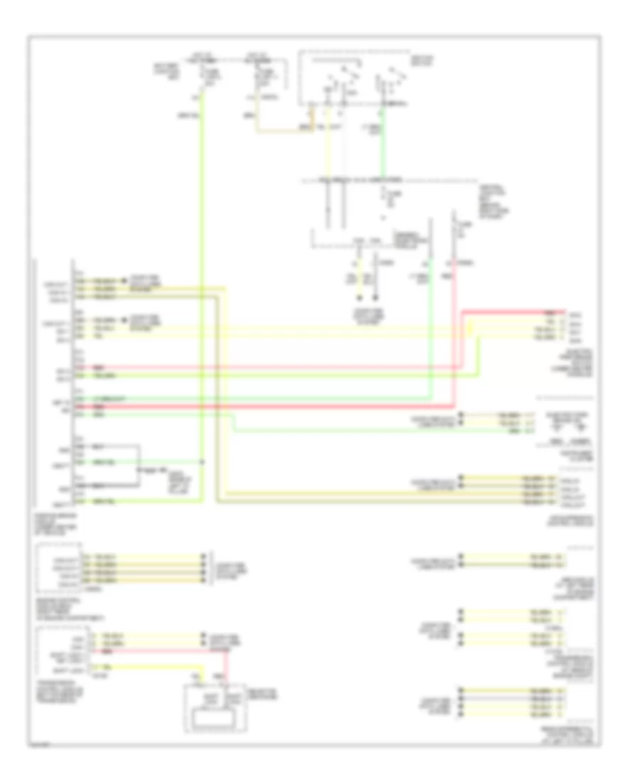
Shift Interlock Wiring Diagram for Land Rover Range Rover Sport Supercharged 2006
List of elements for Shift Interlock Wiring Diagram for Land Rover Range Rover Sport Supercharged 2006:
- (amber)
- (red)
- Abs module (at left rear of engine compartment)
- Acc
- Air suspension control module
- Battery junction box
- C0193
- C0570l
- C0580
- C0582
- C0585l
- C0635l
- C1319l
- C1854l
- C2570 (base of left "d" pillar)
- Can +
- Can -
- Can in +
- Can in -
- Can in+
- Can in-
- Can out +
- Can out -
- Can out+
- Can out-
- Can_in
- Can_out
- Central junction box (behind right side of dash)
- Computer data lines system
- Electric park brake ind
- Electric park brake switch (under center console)
- Engine control module (ecm) (right rear of engine compartment)
- Fuse 5a
- Fuse link 11 30a
- Fuse link 8 30a
- Generic electronic module
- Gnd
- Hot at all times
- Ign
- Ignition switch
- Instrument cluster
- Key in
- Key-in
- Parking brake module (under center of vehicle)
- Rear differential control module (at left "c" pillar)
- Red
- Selector mechanism
- Shift lock +
- Shift lock +/ key lock +
- Shift lock -
- Sw 1
- Sw 2
- Sw 4
- Sw 5
- Sw1
- Sw2
- Sw4
- Sw5
- Transfer box control module (at rear of engine compt)
- Transmission control module (bottom rear of transmission)
- Vbatt
 Čeština
 Dansk
Dansk Deutsch
 Ελληνικά
 English
 Español
 Suomi
Suomi Français
 Français
 עברית
עברית Hrvatski
 Magyar
 Italiano
 日本語
日本語 한국어
한국어 Nederlands
 Polski
 Português
 Português
 Română
 Русский
 Slovenčina
 Slovenščina
 Svenska
 Türkçe
 中文 (中国)
 English