SHIFT INTERLOCK
Shift Interlock Wiring Diagram, with CVT for Mitsubishi Lancer Ralliart 2009
 https://portal-diagnostov.com/license.html
Automotive Electricians Portal FZCO
Automotive Electricians Portal FZCO
https://portal-diagnostov.com/license.html
https://portal-diagnostov.com/license.html
Automotive Electricians Portal FZCO
Automotive Electricians Portal FZCO
List of elements for Shift Interlock Wiring Diagram, with CVT for Mitsubishi Lancer Ralliart 2009:
- (behind left kick panel) g14
- C-304
- C-317
- Etacs-ecu (on rear of junction block, behind left end of dash)
- Fuse 15a
- Fuse 7.5a
- Hot at all times
- Hot in on or start
- Ig1 relay
- P range detection switch
- Red
- Shift lock control relay
- Shift lock solenoid
- Shift switch assembly (center console)
- Stoplight switch (under left side of dash)
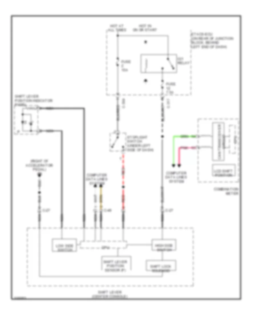
Shift Interlock Wiring Diagram, with TC-SST for Mitsubishi Lancer Ralliart 2009
List of elements for Shift Interlock Wiring Diagram, with TC-SST for Mitsubishi Lancer Ralliart 2009:
- (right of accelerator pedal) g5
- C-27
- C-304
- C-317
- C-49
- Can transceiver
- Circuit
- Combination meter
- Computer data lines system
- Cpu
- Etacs-ecu (on rear of junction block, behind left end of dash)
- Fuse 15a
- Fuse 7.5a
- High side switch
- Hot at all times
- Hot in on or start
- Ig1 relay
- Lcd shift position
- Low side switch
- Nca
- Pnk
- Red
- Shift lever (center console)
- Shift lever position indicator panel
- Shift lever position sensor (p)
- Shift lock solenoid
- Stoplight switch (under left side of dash)

 Čeština
 Dansk
Dansk Deutsch
 Ελληνικά
 English
 Español
 Suomi
Suomi Français
 Français
 עברית
עברית Hrvatski
 Magyar
 Italiano
 日本語
日本語 한국어
한국어 Nederlands
 Polski
 Português
 Português
 Română
 Русский
 Slovenčina
 Slovenščina
 Svenska
 Türkçe
 中文 (中国)