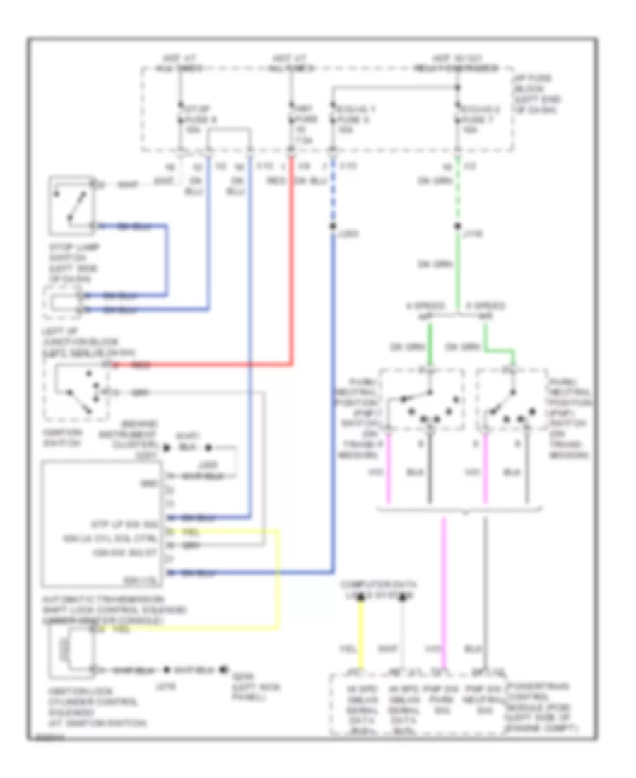
SHIFT INTERLOCK
Shift Interlock Wiring Diagram for Pontiac Vibe 2010
 https://portal-diagnostov.com/license.html
Automotive Electricians Portal FZCO
Automotive Electricians Portal FZCO
https://portal-diagnostov.com/license.html
https://portal-diagnostov.com/license.html
Automotive Electricians Portal FZCO
Automotive Electricians Portal FZCO
List of elements for Shift Interlock Wiring Diagram for Pontiac Vibe 2010:
- (behind instrument cluster) g201
- 4 speed a/t
- 5 speed a/t
- Am1 fuse 7.5a
- Automatic transmission shift lock control solenoid (under center console)
- Computer data lines system
- Ecu-ig 1 fuse 6 10a
- Ecu-ig 2 fuse 7 10a
- G200 (left kick panel)
- Gnd
- Hi spd gmlan serial data bus+
- Hi spd gmlan serial data bus-
- Hot at all times
- Hot w/ ig1 relay energized
- I/p fuse block (left end of dash)
- Ign lk cyl sol ctrl
- Ign sw sig st
- Ign vol
- Ignition lock cylinder control solenoid (at ignition switch)
- Ignition switch
- J116
- J203
- J205
- J219
- Left i/p junction block (left side of dash)
- Park/ neutral position (pnp) switch (on trans- mission)
- Pnp sw neutral sig
- Pnp sw park sig
- Powertrain control module (pcm) (left side of engine compt)
- Red
- Stop fuse 9 10a
- Stop lamp switch (left side of dash)
- Stp lp sw sig
- X13
 Čeština
 Dansk
Dansk Deutsch
 Ελληνικά
 English
 English
 Español
 Suomi
Suomi Français
 Français
 Hrvatski
 Magyar
 Italiano
 日本語
日本語 한국어
한국어 Nederlands
 Polski
 Português
 Português
 Română
 Русский
 Slovenčina
 Slovenščina
 Svenska
 Türkçe
 中文 (中国)
 עברית
עברית
