SHIFT INTERLOCK
Shift Interlock Wiring Diagram for Saturn Ion 3 2006
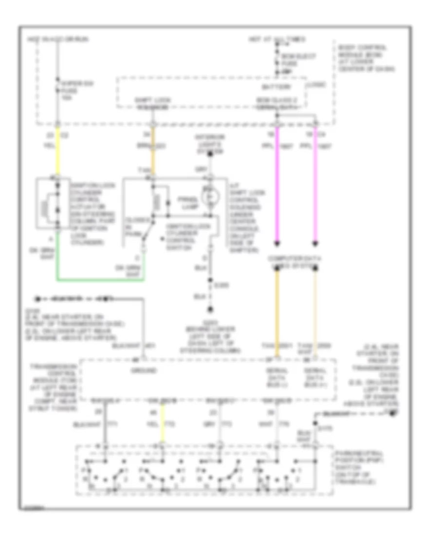
List of elements for Shift Interlock Wiring Diagram for Saturn Ion 3 2006:
- (2.4l: near starter, on front of transmission case) (2.2l: on lower left rear of engine, above starter) g105
- A/t shift lock control solenoid (under center console, on left side of shifter)
- Battery
- Bcm class 2 serial data
- Bcm elect fuse 20a
- Body control module (bcm) (at lower center of dash)
- Closes in park
- Computer data lines system
- G105 (2.4l: near starter, on front of transmission case) (2.2l: on lower left rear of engine, above starter)
- G203 (behind lower left side of dash, left of steering column)
- Ground
- Hot at all times
- Hot in acc or run
- Ignition lock cylinder control actuator (on steering column, part of ignition lock cylinder)
- Ignition lock cylinder control switch
- Interior lights system
- Logic
- Park/neutral position (pnp) switch (on top of transaxle)
- Prndl lamp
- R n
- S175
- S355
- Serial data bus (+)
- Serial data bus (-)
- Shift lock solenoid
- Sw sig a
- Sw sig b
- Sw sig c
- Sw sig d
- Tan
- Tan b
- Tan/
- Transmission control module (tcm) (at left rear of engine compt, near strut tower)
- Wiper sw fuse 10a
 Čeština
 Dansk
Dansk Deutsch
 Ελληνικά
 English
 English
 Español
 Suomi
Suomi Français
 Français
 עברית
עברית Hrvatski
 Magyar
 Italiano
 日本語
日本語 한국어
한국어 Nederlands
 Polski
 Português
 Română
 Русский
 Slovenčina
 Slovenščina
 Svenska
 Türkçe
 中文 (中国)
 Português