
 Čeština
 Dansk
Dansk Deutsch
 Ελληνικά
 English
 Español
 Suomi
Suomi Français
 Français
 עברית
עברית Hrvatski
 Magyar
 Italiano
 日本語
日本語 한국어
한국어 Nederlands
 Polski
 Português
 Português
 Română
 Русский
 Slovenčina
 Slovenščina
 Svenska
 Türkçe
 中文 (中国)

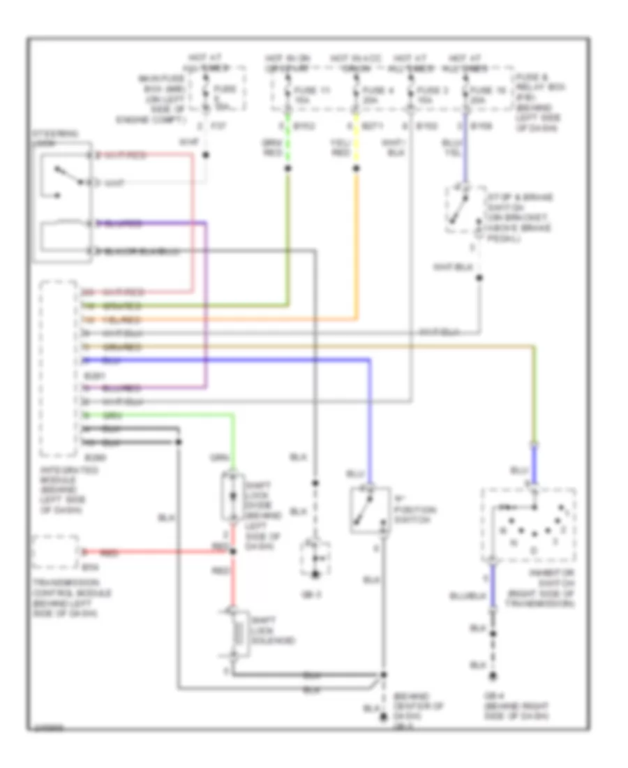
SHIFT INTERLOCK
Shift Interlock Wiring Diagram for Subaru Impreza WRX STi 2006
List of elements for Shift Interlock Wiring Diagram for Subaru Impreza WRX STi 2006:

ANTI-LOCK BRAKESAIR CONDITIONINGBODY CONTROL MODULESENGINE PERFORMANCECOOLING FANANTI-THEFTDEFOGGERSCRUISE CONTROLCOMPUTER DATA LINESHORNEXTERIOR LIGHTSHEADLIGHTSGROUND DISTRIBUTIONPOWER DISTRIBUTIONSHIFT INTERLOCKPOWER MIRRORSRADIOINTERIOR LIGHTSPOWER WINDOWSPOWER TOP/SUNROOFPOWER DOOR LOCKSINSTRUMENT CLUSTERPOWER SEATSSTARTING/CHARGINGTRANSMISSIONWARNING SYSTEMSSUPPLEMENTAL RESTRAINTSWIPER/WASHER