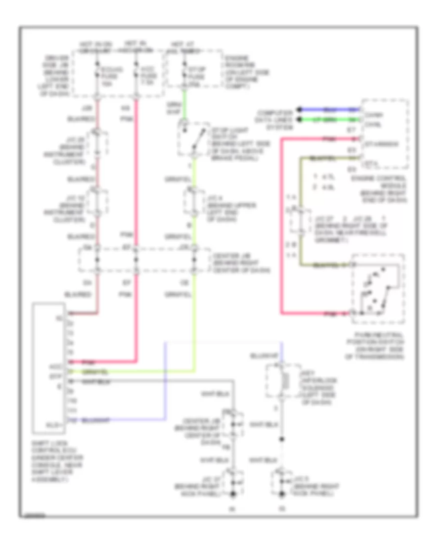
SHIFT INTERLOCK
Shift Interlock Wiring Diagram for Toyota 4Runner SR5 2008
List of elements for Shift Interlock Wiring Diagram for Toyota 4Runner SR5 2008:
- 4.0l
- 4.7l
- Acc
- Acc fuse 7.5a
- Canh
- Canl
- Center j/b (behind right center of dash)
- Computer data lines system
- Driver side j/b (behind lower left end of dash)
- Ecu-ig fuse 10a
- Engine control module (behind right end of dash)
- Engine room r/b (on left side of engine compt)
- Hot at all times
- Hot in acc or on
- Hot in on or start
- J/c 12 (behind instrument cluster)
- J/c 20 (behind instrument cluster)
- J/c 27 (behind right side of dash, near firewell grommet)
- J/c 28
- J/c 37 (behind right kick panel)
- J/c 4 (behind upper left end of dash)
- J/c 5 (behind right kick panel)
- J28
- Key interlock solenoid (left side of dash)
- Kls+
- Park/neutral position switch (on right side of transmission)
- Pnk
- Shift lock control ecu (under center console, near shift lever assembly)
- Sta
- Star/nsw
- Stop fuse 10a
- Stop light switch (behind left side of dash, above brake pedal)
- Stp
 Čeština
 Dansk
Dansk Deutsch
 Ελληνικά
 English
 English
 Español
 Suomi
Suomi Français
 עברית
עברית Hrvatski
 Magyar
 Italiano
 日本語
日本語 한국어
한국어 Nederlands
 Polski
 Português
 Português
 Română
 Русский
 Slovenčina
 Slovenščina
 Svenska
 Türkçe
 中文 (中国)
 Français