
 Čeština
 Dansk
Dansk Ελληνικά
 English
 English
 Español
 Suomi
Suomi Français
 Français
 עברית
עברית Hrvatski
 Magyar
 Italiano
 日本語
日本語 한국어
한국어 Nederlands
 Polski
 Português
 Português
 Română
 Русский
 Slovenčina
 Slovenščina
 Svenska
 Türkçe
 中文 (中国)

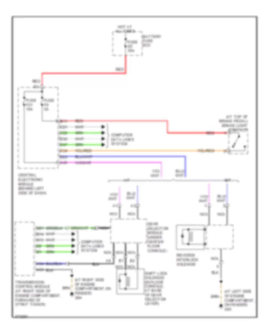
SHIFT INTERLOCK
Shift Interlock Wiring Diagram for Volvo S60 2009
List of elements for Shift Interlock Wiring Diagram for Volvo S60 2009:

ANTI-LOCK BRAKESCOMPUTER DATA LINESCOOLING FANDEFOGGERSANTI-THEFTCRUISE CONTROLBODY CONTROL MODULESENGINE PERFORMANCEELECTRONIC POWER STEERINGINTERIOR LIGHTSHORNHEADLIGHTSMEMORY SYSTEMSPOWER DOOR LOCKSPOWER DISTRIBUTIONPOWER WINDOWSPOWER MIRRORSSHIFT INTERLOCKSTARTING/CHARGINGPOWER TOP/SUNROOFRADIOTRANSMISSIONSUPPLEMENTAL RESTRAINTSWARNING SYSTEMSWIPER/WASHERAIR CONDITIONINGEXTERIOR LIGHTSINSTRUMENT CLUSTERGROUND DISTRIBUTIONNAVIGATION