
 Čeština
 Dansk
Dansk Deutsch
 Ελληνικά
 English
 Español
 Suomi
Suomi Français
 Français
 עברית
עברית Hrvatski
 Magyar
 Italiano
 日本語
日本語 한국어
한국어 Nederlands
 Polski
 Português
 Português
 Română
 Русский
 Slovenčina
 Slovenščina
 Svenska
 Türkçe
 中文 (中国)

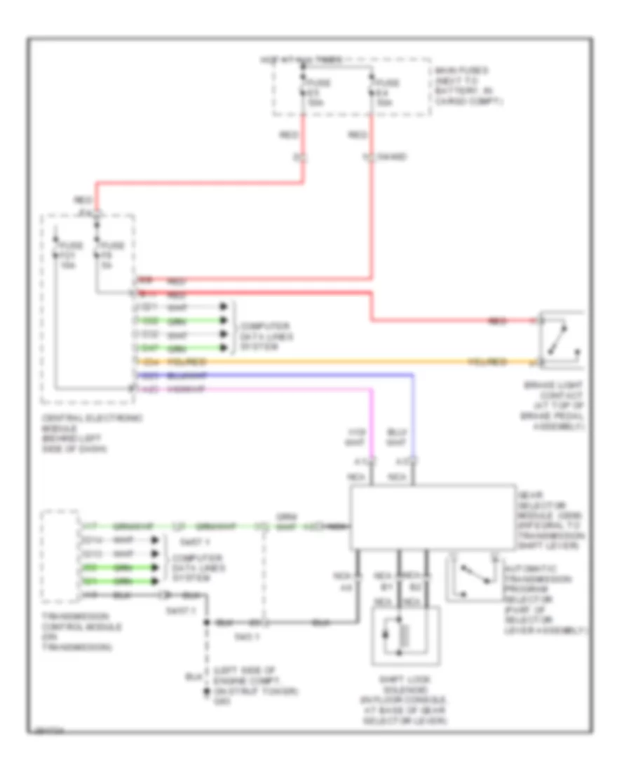
SHIFT INTERLOCK
Shift Interlock Wiring Diagram for Volvo XC90 2012
List of elements for Shift Interlock Wiring Diagram for Volvo XC90 2012:

COMPUTER DATA LINESBODY CONTROL MODULESAIR CONDITIONINGANTI-THEFTCRUISE CONTROLELECTRONIC POWER STEERINGDEFOGGERSCOOLING FANHEADLIGHTSENGINE PERFORMANCEEXTERIOR LIGHTSINSTRUMENT CLUSTERGROUND DISTRIBUTIONHORNMEMORY SYSTEMSNAVIGATIONINTERIOR LIGHTSPOWER DOOR LOCKSPOWER DISTRIBUTIONPOWER SEATSPOWER WINDOWSRADIOSHIFT INTERLOCKPOWER TOP/SUNROOFSTARTING/CHARGINGWARNING SYSTEMSTRANSMISSIONWIPER/WASHERSUPPLEMENTAL RESTRAINTSANTI-LOCK BRAKES