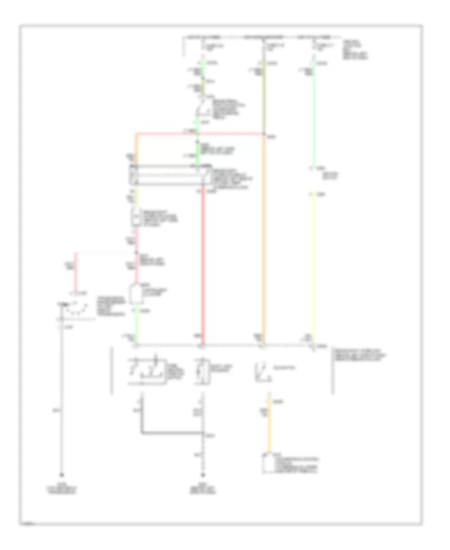
SHIFT INTERLOCKS
Shift Interlock Wiring Diagram for Ford Escape 2001
List of elements for Shift Interlock Wiring Diagram for Ford Escape 2001:
- Brake pedal position switch (on bracket above brake pedal)
- Brake shift interlock diode (behind left side of dash)
- Brake shift interlock (behind left side of dash, near steering column)
- Brake shift interlock relay (behind left side of of dash, near steering column)
- C167
- C175
- C2008
- C2068
- C220b
- C250
- C270c
- C270d
- C270e
- C278
- Central junction box (behind left end of dash)
- Fuse 2.11 10a
- Fuse 2.16 10a
- Fuse 2.24 15a
- G129 (top center of transmission)
- G202 (behind left side of dash)
- Hot at all times
- Hot in run or start
- Ignition switch
- Instrument cluster
- O/d switch
- Park
- Park neutral position switch
- Powertrain control module (in recess on upper center of firewall)
- Red
- S218
- S218 (behind left side of dash)
- S222
- S226 (behind left side, bottom of dash)
- S314
- Shift lock solenoid
- Transmission range sensor (on left side of transmission)
 Čeština
 Dansk
Dansk Deutsch
 Ελληνικά
 English
 Español
 Suomi
Suomi Français
 Français
 עברית
עברית Hrvatski
 Magyar
 Italiano
 日本語
日本語 한국어
한국어 Nederlands
 Polski
 Português
 Português
 Română
 Русский
 Slovenčina
 Slovenščina
 Svenska
 Türkçe
 中文 (中国)
 English