SHIFT INTERLOCKS
Shift Interlock Wiring Diagram, Commercial Chassis for GMC Vandura P3500 1997
 https://portal-diagnostov.com/license.html
Automotive Electricians Portal FZCO
Automotive Electricians Portal FZCO
https://portal-diagnostov.com/license.html
https://portal-diagnostov.com/license.html
Automotive Electricians Portal FZCO
Automotive Electricians Portal FZCO
List of elements for Shift Interlock Wiring Diagram, Commercial Chassis for GMC Vandura P3500 1997:
- (below radiator, on crossmember) electronic brake control module
- (left interior bulkhead, near relay bracket or body builder installed) g202
- Brake
- Brake/transmission shift interlock (btsi) relay (left interior bulkhead on relay bracket)
- Brake/transmission shift interlock (btsi) solenoid (on steering column)
- Diesel
- Gasoline
- Hot in run
- I-3 fuse 15a
- I/p fuse block
- Ign
- Park/neutral position and backup lamps switch (left of trans)
- S110
- S133 (gas) s124 (diesel)
- S200 (i/p side of eng harn, approx 17 cm from grommet left of bulkhead conn)
- Torque converter clutch and stop lamps switch (right side of steering column)
- Trans- mission control module (left interior bulkhead)
- Turn b/u fuse 15a
- Turn signal flasher (on fuse block)
- Vehicle control module (left radiator support)
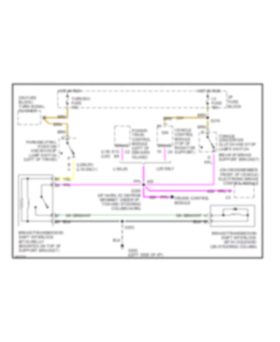
Shift Interlock Wiring Diagram, Motor Home Chassis for GMC Vandura P3500 1997
List of elements for Shift Interlock Wiring Diagram, Motor Home Chassis for GMC Vandura P3500 1997:
- (l19) (l65)
- (l29/l65) (l19 only)
- (on crossmember, front of vehicle) electronic brake control module
- (on fuse block) turn signal flasher
- (rear of brake support bracket)
- B a
- Brake
- Brake/transmission shift interlock (btsi) relay (mounted on top of support bracket)
- Brake/transmission shift interlock (btsi) solenoid (on steering column)
- Cruise control module
- E13 b9
- G202 (left side of i/p)
- Hot in run
- I-3 fuse 15a
- I/p fuse block
- Ign
- L19/l65
- L29 only
- Park/neutral position and backup lamp switch (left of trans)
- Power- train control module (left of driver's island)
- S200 (i/p harn, 22 cm from grommet under i/p, toward steering column harn)
- S203
- S216
- Torque converter clutch and stop lamps switch
- Turn b/u fuse 15a
- Vehicle control module (top of radiator support)

 Čeština
 Dansk
Dansk Deutsch
 Ελληνικά
 English
 Español
 Suomi
Suomi Français
 Français
 עברית
עברית Hrvatski
 Magyar
 Italiano
 日本語
日本語 한국어
한국어 Nederlands
 Polski
 Português
 Português
 Română
 Русский
 Slovenčina
 Slovenščina
 Svenska
 Türkçe
 中文 (中国)