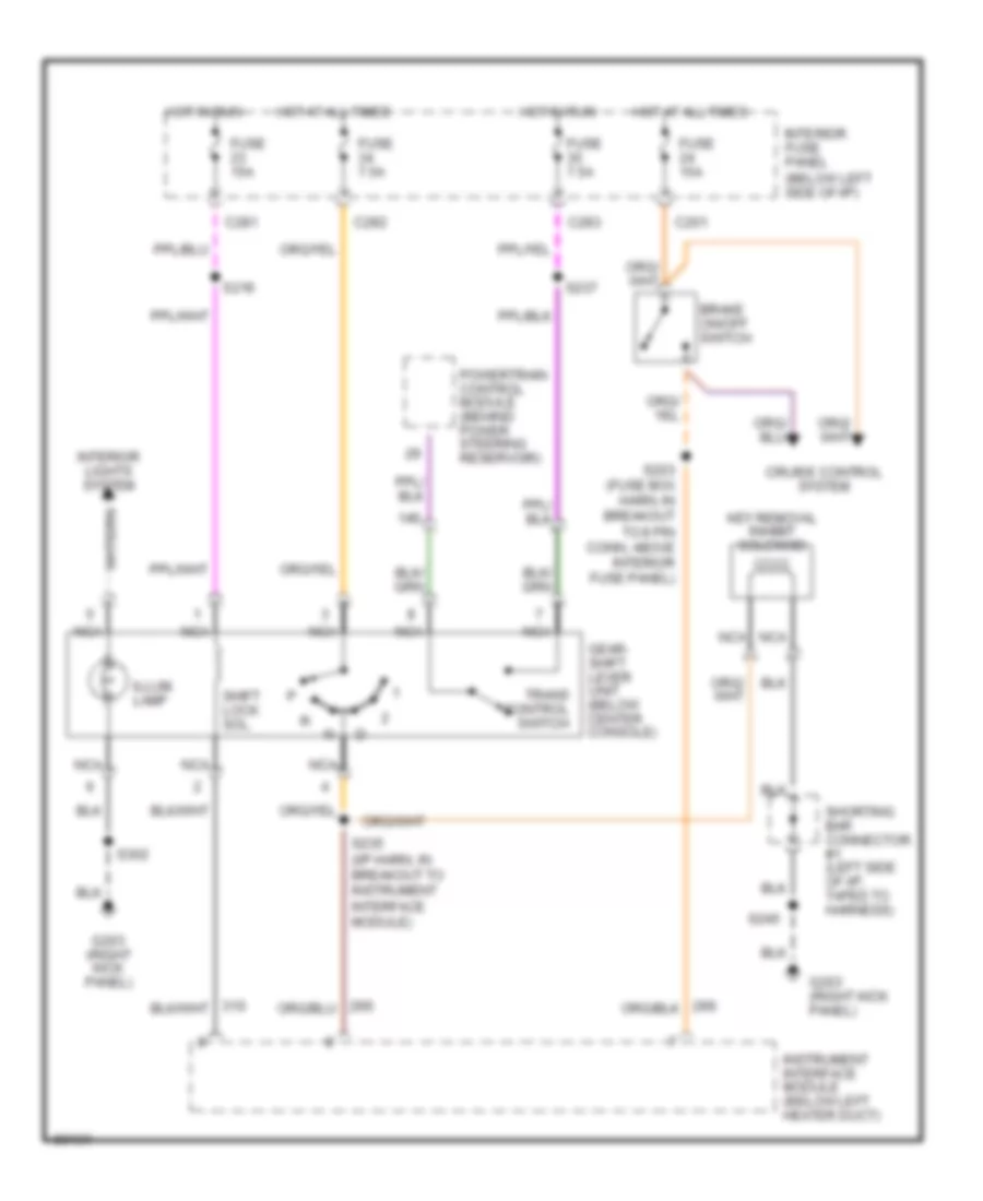
SHIFT INTERLOCKS
Shift Interlock Wiring Diagram for Mercury Mystique 1997
List of elements for Shift Interlock Wiring Diagram for Mercury Mystique 1997:
- 14s
- Brake on/off switch
- C201
- C281
- C282
- C283
- Cruise control system
- Fuse 15a
- Fuse 7.5a
- G203 (right kick panel)
- Gear- shift lever unit (below center console)
- Hot at all times
- Hot in run
- Illum. lamp
- Instrument interface module (below left heater duct)
- Interior fuse panel (below left side of i/p)
- Interior lights system
- Key removal inhibit solenoid
- Nca
- Powertrain control module (behind power steering reservoir)
- S203 (fuse box harn, in breakout to 8 pin conn, above interior fuse panel)
- S216
- S235 (i/p harn, in breakout to instrument interface module)
- S237
- S245
- S302
- Shift lock sol.
- Shorting bar connector #1 (left side of i/p, taped to harness)
- Trans control switch
 Čeština
 Dansk
Dansk Deutsch
 Ελληνικά
 English
 English
 Español
 Suomi
Suomi Français
 Français
 עברית
עברית Hrvatski
 Magyar
 Italiano
 日本語
日本語 한국어
한국어 Nederlands
 Polski
 Português
 Português
 Română
 Русский
 Slovenščina
 Svenska
 Türkçe
 中文 (中国)
 Slovenčina